Resistance calculator for LEDs. LED calculator online. Calculation and selection of resistance for an LED. Programs for calculating resistance
An LED is a nonlinear semiconductor device that requires a stable current for proper and reliable operation. Overcurrent may damage the LED. The simplest version of the power supply circuit in this case is a limiting resistor connected in series. Calculating the nominal resistance and power of a resistor for an LED is not a very difficult task if you correctly understand the physics of the process. Let's look at the general principles of such calculations, and then look at several specific examples from practice.
Theory
In general, the scheme looks like this.
Picture 1
Voltage is applied between the “+” and “-” contacts. Let's denote it by the letter U. The current through the resistor and the LED will flow the same, because serial connection. According to Ohm's law we get:

where R is the resistance of the resistor;
r LED – LED resistance (differential).
From here we express the formula by which we can calculate the resistance of the resistor R at a given current I:

Let's figure out what the differential resistance of an LED r LED is. To do this, we need its current-voltage characteristic (volt-ampere characteristic).

Figure 2
As can be seen from the graphs, the current-voltage characteristics of LEDs are nonlinear. In simple terms, its resistance to direct current r=U/I is a variable value that decreases with increasing voltage. Therefore, the concept of differential resistance r LED = dU/dI is introduced, which characterizes the resistance of the diode at a particular point on the current-voltage characteristic curve.
To calculate the resistor for an LED, we determine from the graph the forward voltage on the LED U LED at a given current I. Then we substitute the resulting value into formula (2) and get

Another way to solve the problem is graphically.
To do this, first, on the graph of the LED’s current-voltage characteristic, we mark a point corresponding to a current of 100 mA (see Figure 3), then draw a load line through this point and the point corresponding to 5 volts on the abscissa axis until it intersects with the ordinate axis. We determine the current value corresponding to this intersection (in our case 250 mA) and, according to Ohm’s law, calculate the resistance of the resistor R = U / I short = 5 V / 0.25 A = 20 Ohm. Before calculating, do not forget to convert the units of measurement to the proper form.

Figure 3
The next step is to determine the power dissipated by the resistor. The formula should be familiar to everyone from school physics (like Ohm’s law):
Practice
Let's consider a somewhat specific example of calculation.
Initial data: supply voltage 12V, white XPE LED () must be turned on at a rated current of 350 mA according to the diagram presented in Figure 1.
We find in the data sheet the value of the forward voltage drop at a current of 350 mA (Figure 4).

Figure 4
The typical value according to the table is 3.2 volts. The maximum value can reach 3.9 volts. That is, as a result of the production process, either an LED with a direct voltage of 3.2 V or 3.9 V (or any other intermediate value) can be obtained, but the probability of obtaining 3.2 volts is the highest (if you want, this is the “mathematical expectation” of this quantities). For this reason, the typical value is usually taken into account.
Using formula (3) and a calculator we get:
R=(12-3.2)/0.35"25.1 Ohm.
The closest value from the E24 series is 24 Ohms. The current value at this resistance will be 367 mA, which is 5% higher than the required value. If we also take into account the tolerance on the resistor value, which for the E24 series is also 5%, then in the worst case we get a total of 386 mA. If such a deviation is not acceptable, then you can add another 1 Ohm resistor in series to the circuit. It is recommended to accompany all these actions with real measurements of the resistor resistances and the resulting currents, otherwise there can be no talk of any accuracy. A 24 Ohm resistor can have an error upward to 25.2 Ohms, adding 1 Ohm, we get 26.2 and the current through the LED “skews” in the opposite direction.
Let's assume that we do not need high accuracy in setting the current and a 24 Ohm resistor suits us.
Let us determine the power that will be dissipated by the resistor using formula (4):
P=0.367 2 ×24"3.2 W.
The rated power dissipation of the resistor must be with a margin of at least 30%, otherwise it will overheat. And if the conditions for heat removal are difficult (for example, there is poor convection in the case), then the reserve should be even greater.
As a result, we select a 5 W resistor with a nominal resistance of 24 Ohms.
In order to evaluate the effectiveness of the resulting lighting device, it is necessary to calculate the efficiency of the power circuit:
Thus, the efficiency of such a power supply circuit is only 27%. This low efficiency is due to the too high supply voltage of 12 volts, or rather the difference between U and U LED. It turns out that we are forced to “quench” 8.8 volts with a resistor due to useless dissipation of power into the surrounding space. To increase efficiency, you need to either reduce the supply voltage or find an LED with a higher forward voltage. Alternatively, you can turn on several LEDs in series, selecting them in such a way that the total drop is closer to the supply voltage, but in no case exceeds it.
The required resistance value for the resistor can be selected if a resistance magazine and an ammeter are available. We connect the magazine and the ammeter in the circuit in series with the LED (in place of the supposed resistor), set the maximum resistance value and connect it to a voltage source. Next, we begin to reduce the resistance value until the current reaches the desired value or the LED reaches the desired brightness (depending on what is the criterion). All that remains is to read the resistance value from the magazine and select the closest value.
Remarque
In these calculations, we neglected the dependence of the forward voltage of the LED on its temperature, but we should not forget that such a dependence exists and is characterized by the parameter “temperature coefficient of voltage” or abbreviated TKN. Its value differs for different types of LEDs, but always has a negative value. This means that as the temperature of the crystal increases, the forward voltage across it becomes less. For example, for the white XPE LED discussed above, the TKN value (it is given by the manufacturer in the data sheet) is -4 mV/°C. Therefore, when the crystal temperature increases by 25°C, the forward voltage across it will decrease by 0.1 V.

Figure 5
Many leading LED manufacturers have a special service on their official websites - an “online calculator”, designed to calculate the parameters of LEDs in various operating modes (depending on temperature, current, etc.). This tool greatly simplifies the calculation procedures and saves time for the developer.
Light-emitting diodes are characterized by a number of operational parameters:
- Rated (operating) current – I n;
- voltage drop at rated current – U n;
- maximum power dissipation – P max;
- maximum permissible reverse voltage – U arr.
The most important of these parameters is operating current.
When the rated operating current flows through the LED, the rated luminous flux, operating voltage and rated power dissipation are set automatically. In order to set the LED operating mode, it is enough to set the rated current of the LED.
In theory, LEDs need to be connected to constant current sources. However, in practice, LEDs are connected to constant voltage sources: batteries, transformers with rectifiers or electronic voltage converters (drivers).
To set the operating mode of the LED, the simplest solution is used - a current-limiting resistor is connected in series with the LED. They are also called damping or ballast resistors.
Let's look at how to calculate the resistor resistance for an LED.
Calculation of LED resistor (using formulas)
When calculating, two quantities are calculated:
- Resistance (value) of the resistor;
- power dissipated by it P.
The voltage sources powering the LEDs have different output voltages. In order to select a resistor for an LED, you need to know the source voltage (U source), the operating voltage drop across the diode and its rated current. The formula for calculation is as follows:
R = (U source - U n) / I n
When we subtract the nominal voltage drop across the LED from the source voltage, we get the voltage drop across the resistor. Dividing the resulting value by the current, according to Ohm's law, we obtain the value of the current-limiting resistor. We substitute the voltage expressed in volts, the current in amperes and get the nominal value expressed in ohms.
The electrical power dissipated by the damping resistance is calculated using the following formula:
P = (I n) 2 ⋅ R
Based on the obtained value, the power of the ballast resistor is selected. For reliable operation of the device, it must be higher than the calculated value. Let's look at an example of a calculation.
Example of calculating a resistor for a 12 V LED
Let's calculate the resistance for an LED powered by a 12V DC voltage source.
Let's say we have at our disposal a popular super-bright SMD 2835 (2.8mm x 3.5mm) with an operating current of 150mA and a voltage drop of 3.2V. SMD 2835 has an electrical power of 0.5 watts. Let's substitute the original values into the formula.
R = (12 - 3.2) / 0.15 ≈ 60
We find that a quenching resistor with a resistance of 60 Ohms is suitable. The closest value from the standard E24 series is 62 ohms. Thus, for the LED we have chosen, we can use a ballast with a resistance of 62 Ohms.
Now let's calculate the power dissipation across the resistance.
P = (0.15) 2 ⋅ 62 ≈ 1.4
Almost one and a half watts of electrical power will be dissipated at the resistance we have chosen. This means that for our purposes we can use a resistor with a maximum permissible power dissipation of 2W.
All that remains is to buy a resistor with a suitable value. If you have old boards from which parts can be desoldered, then you can select a resistor based on the color marking. Use the form below.
On a note! In the example above, the current limiting resistor dissipates almost three times as much energy as the LED. This means that taking into account the luminous efficiency of the LED, the efficiency of our design is less than 25%.
To reduce energy losses, it is better to use a source with a lower voltage. For example, you can use an AC/AC 12/5 volt DC/DC converter for power supply. Even taking into account the efficiency of the converter, the losses will be significantly less.
Parallel connection
Quite often it is necessary to connect several diodes to one source. Theoretically, to power several parallel-connected LEDs, one current-limiting resistor can be used. In this case, the formulas will look like this:
R = (U source - U n) / (n ⋅ I n)
P = (n ⋅ I n) 2 ⋅ R
Wheren– the number of LEDs connected in parallel.
Why can't you use one resistor for several parallel diodes?
Even in “Chinese” products, manufacturers install a separate current-limiting resistor for each LED. The fact is that in the case of a common ballast for several LEDs, the probability of failure of light-emitting diodes increases many times over.
If one of the semiconductors breaks, its current will be redistributed through the remaining LEDs. The power dissipated on them will increase and they will begin to heat up intensely. Due to overheating, the next diode will fail and the process will then take on an avalanche-like character.
Advice. If for some reason you need to make do with one damping resistor, increase its value by 20-25%. This will ensure greater reliability of the design.

Is it possible to do without resistors?
Indeed, in some cases it is possible not to use a current-limiting resistor. The LED we reviewed can be directly powered by two 1.5V batteries. Since its operating voltage is 3.2V, the current flowing through it will be less than the rated one and it will not require ballast. Of course, with such power supply, the LED will not produce the full luminous flux.
Sometimes in alternating current circuits capacitors are used instead of resistors as current-limiting elements (more about). An example is backlit switches in which the capacitors are “watt-free” resistances.
An ordinary small LED looks like a plastic lens cone on conductive legs, inside which there is a cathode and an anode. In the diagram, the LED is depicted as a regular diode, from which the arrows show the light emitted. So the LED serves to produce light when electrons move from the cathode to the anode - visible light is emitted.
The invention of the LED dates back to the distant 1970s, when incandescent lamps were used to produce all the light. But today, at the beginning of the 21st century, LEDs have finally taken the place of the most efficient sources of electric light.
Where is the “plus” of the LED and where is the “minus”?
To properly connect an LED to a power source, you must first observe the polarity. The anode of the LED is connected to the plus “+” of the power supply, and the cathode is connected to the minus “-”. The cathode connected to the minus has a short lead, the anode, accordingly, has a long lead - the long leg of the LED - to the plus “+” of the power source.
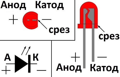
Take a look inside the LED: the large electrode is the cathode, its is the minus, the small electrode, which just looks like the end of a leg, is the plus. And next to the cathode, the LED lens has a flat cut.
Do not hold the soldering iron on the leg for a long time
The leads of the LED should be soldered carefully and quickly, because the semiconductor junction is very afraid of excess heat, so you need to briefly touch the tip of the soldering iron with its tip to the soldered leg, and then move the soldering iron to the side. It is better to hold the soldered LED leg with tweezers during the soldering process to ensure that heat is removed from the leg, just in case.
A resistor is required when testing an LED

We come to the most important thing - how to connect an LED to a power source. If you want, then you should not directly connect it to the battery or power supply. If your power supply is 12 volts, then use a 1 kOhm resistor in series with the LED being tested for backup.
Do not forget about polarity - the long lead is positive, the lead from the large internal electrode is negative. If you do not use a resistor, the LED will quickly burn out; if you accidentally exceed the rated voltage, a large current will flow through the p-n junction, and the LED will almost immediately fail.
LEDs come in a variety of colors, but the color of the light is not always determined by the color of the LED lens. White, red, blue, orange, green or yellow - the lens can be transparent, but when you turn it on, it turns out to be red or blue. Blue and white LEDs are the most expensive. In general, the color of the LED glow is influenced primarily by the composition of the semiconductor, and as a secondary factor by the color of the lens.

Finding the resistor value for the LED
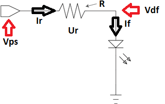
The resistor is connected in series with the LED. The function of the resistor is to limit the current, make it close to the nominal value of the LED, so that the LED does not instantly burn out, and operates in normal nominal mode. We take into account the following initial data:
Vps - power supply voltage;
Vdf - forward voltage drop across the LED in normal mode;
If - rated current of the LED in normal lighting mode.
Now, before finding , we note that the current in the series circuit will be constant, the same in each element: the current If through the LED will be equal to the current Ir through the limiting resistor.
Therefore Ir = If. But Ir = Ur/R - according to Ohm's law. A Ur = Vps-Vdf. Thus, R = Ur/Ir = (Vps-Vdf)/If.
That is, knowing the voltage of the power supply, the voltage drop across the LED and its rated current, you can easily select a suitable limiting resistor.
If the found resistance value cannot be selected from the standard range of resistor values, then take a resistor of a slightly larger value, for example, instead of the found 460 Ohms, take 470 Ohms, which are always easy to find. The brightness of the LED will decrease very slightly.
Example of resistor selection:
Let's say there is a 12 volt power supply and an LED that needs 1.5 volts and 10 mA to glow normally. Let's select a quenching resistor. The resistor should drop 12-1.5 = 10.5 volts, and the current in the series circuit (power supply, resistor, LED) should be 10 mA, therefore from Ohm’s Law: R = U/I = 10.5/0.010 = 1050 Ohm. Select 1.1 kOhm.
What power should the resistor be? If R = 1100 Ohms and the current is 0.01 A, then, according to the Joule-Lenz law, thermal energy Q = I*I*R = 0.11 J will be released on the resistor every second, which is equivalent to 0.11 W. A resistor with a power of 0.125 W will do, there will even be some reserve.
Series connection of LEDs
If your goal is to connect several LEDs into a single light source, then it is best to make the connection in series. This is necessary so that each LED does not have its own resistor to avoid unnecessary energy losses. LEDs of the same type, from the same batch, are most suitable for serial connection.
Let's say you need to connect 8 LEDs of 1.4 volts each with a current of 0.02 A in series to connect to a 12 volt power source. Obviously, the total current will be 0.02 A, but the total voltage will be 11.2 volts, so 0.8 volts at 0.02 A current must be dissipated in the resistor. R = U/I = 0.8/0.02 = 40 Ohm. We select a 43 ohm resistor of minimum power.
Parallel connection of LED chains is not the best option

If you have a choice, it is best to connect LEDs in series rather than in parallel. If you connect several LEDs in parallel through one common resistor, then due to the variation in the parameters of the LEDs, each of them will not be on an equal footing with the others, some will glow brighter, accepting more current, and some, on the contrary, will be dimmer. As a result, one of the LEDs will burn out earlier due to rapid degradation of the crystal. It is better to connect LEDs in parallel, if there is no alternative, to apply its own limiting resistor to each chain.
This article will talk about calculation of current limiting resistor for LED.
Calculation of a resistor for one LED
To power one LED, we need a power source, for example two AA batteries of 1.5V each. Let's take a red LED, where the forward voltage drop at an operating current of 0.02 A (20 mA) is equal to -2 V. For conventional LEDs, the maximum permissible current is 0.02 A. The LED connection diagram is shown in Fig. 1.
Why do I use the term "forward voltage drop", not the supply voltage. But the fact is that LEDs do not have a supply voltage parameter as such. Instead, the voltage drop characteristic of the LED is used, which means the amount of voltage the LED outputs when the rated current passes through it. The voltage value indicated on the packaging reflects the voltage drop. Knowing this value, you can determine the voltage remaining on the LED. This is the value we need to use in our calculations.
The forward voltage drop for various LEDs depending on the wavelength is presented in Table 1.
Table 1 - LED characteristics
The exact value of the LED voltage drop can be found on the packaging for this LED or in the reference literature.
R = (Un.p – Ud)/Id = (3V-2V)/0.02A = 50 Ohm.
- Un.p – supply voltage, V;
- Ud — forward voltage drop across the LED, V;
Since there is no such resistance in the standard series, we select the nearest resistance from the nominal series E24 upward - 51 Ohms.

To guarantee long-term operation of the LED and to eliminate errors in calculations, I recommend using not the maximum permissible current - 20 mA, but a little less - 15 mA.
This reduction in current will not in any way affect the brightness of the LED for the human eye. In order for us to notice a change in the brightness of the LED, for example, by 2 times, we need to reduce the current by 5 times (according to the Weber-Fechner law).
As a result, we get the calculated resistance of the current-limiting resistor: R = 50 Ohms and power dissipation P = 0.02 W (20 mW).
Calculation of a resistor for series connection of LEDs
In the case of calculating a resistor for a series connection, all LEDs must be of the same type. The LED connection diagram for a serial connection is shown in Fig. 2.

For example, we want to connect to a 9 V power supply, three green LEDs, each 2.4 V, operating current - 20 mA.
The resistance of the resistor is determined by the formula:
R = (Un.p – Ud1 + Ud2 + Ud3)/Id = (9V - 2.4V +2.4V +2.4V)/0.02A = 90 Ohm.
- Un.p – supply voltage, V;
- Uд1…Uд3 — forward voltage drop across the LEDs, V;
- Id – operating current of the LED, A.
We select the nearest resistance from the nominal series E24 upward - 91 Ohms.
Calculation of resistors for parallel-series connection of LEDs
Often in practice we need to connect a large number of LEDs, several dozen, to a power source. If all the LEDs are connected in series through one resistor, then in this case the voltage at the power source will not be enough for us. The solution to this problem is a parallel-series connection of LEDs, as shown in Fig. 3.
Based on the power supply voltage, the maximum number of LEDs that can be connected in series is determined.

Fig. 3 – LED connection diagram for parallel - serial connection
For example, we have a 12 V power supply, based on the voltage of the power supply, the maximum number of LEDs for one circuit will be equal to: 10V/2V = 5 pcs, taking into account that the voltage drop across the LED (red) is 2 V.
Why we took 10 V and not 12 V is due to the fact that there will also be a voltage drop across the resistor and we must leave somewhere around 2 V.
The resistor resistance for one circuit, based on the operating current of the LEDs, is determined by the formula:
R = (Un.p – Ud1 + Ud2 + Ud3+ Ud4+ Ud5)/Id = (12V - 2V + 2V + 2V + 2V + 2V)/0.02A = 100 Ohm.
We select the nearest resistance from the nominal range E24 upward - 110 Ohms.
The number of such chains of five LEDs connected in parallel is practically unlimited!
Calculation of a resistor when connecting LEDs in parallel
This connection is not desirable and I do not recommend using it in practice. This is due to the fact that each LED has a technological voltage drop, and even if all the LEDs are from the same package, this is not a guarantee that their voltage drop will be the same due to the production technology.
As a result, one LED will have more current than the others and if it exceeds the maximum permissible current, it will fail. The next LED will burn out faster, since the remaining current will already pass through it, distributed among other LEDs, and so on until all the LEDs fail.

This problem can be solved by connecting its own resistor to each LED, as shown in Fig. 5.

To determine the required current limiting resistor value for one or more LEDs, you will need the following data:
Power supply voltage;
- forward voltage of the LED and the current for which it is designed;
- number and connection diagram of LEDs.
In the absence of reference data, the forward voltage of the LED can be determined quite accurately by the color of its glow using the table:
Most of these modern semiconductor devices are designed for a current of 20 mA, but there are diodes designed for higher currents (150 mA or more). Therefore, to accurately determine the rated current, technical data of the diode brand will be required.
In the complete absence of information about the brand and technical characteristics of the LED, we recommend taking the rated current as 10 mA and the forward voltage as 1.5-2 V.
The required number of quenching resistors depends on the choice of connection diagram for semiconductor devices. So, when they are connected in series, one thing is quite enough: at all points the values of the flowing current are the same.
When connecting diodes in parallel, the use of one common quenching resistor is unacceptable. Due to the fact that there are no LEDs that are completely identical in their characteristics; Having a certain spread in resistance and, accordingly, consumed currents, an element with lower resistance will consume more current, which can cause its premature failure.
Thus, if one of several parallel-connected LEDs burns out, the rest, due to the resistance of a resistor designed for a certain number of diodes, will receive an increased voltage for which they are not designed, which, in turn, will cause them to fail.
Therefore, when connecting LEDs in parallel, it is recommended to provide a separate resistance for each element. This recommendation is taken into account in the proposed calculator.
The calculation is made using the formula:
R=Uquenching/ILED;
Uquenching = Upower – ULED.
Important! Be sure to observe the correct polarity of LED connections. The anode (longer lead) is connected to the plus of the power source, and the cathode is connected to the minus (there is a characteristic cut on the diode bulb on its side).