Driving tractor moving forward backward. Tractor control technology. Generator and voltage regulator
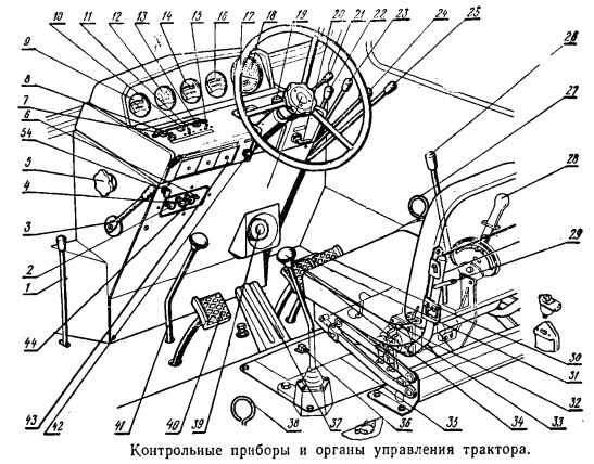
The controls of the MTZ-80 tractor are shown in the figure below.
1 - When the lever is turned toward itself, the gear wheel of the gearbox engages with the flywheel of the main engine, and the clutch is disengaged. When the lever is turned away from itself, the clutch of the gearbox engages. The neutral position of the lever is vertical.
Due to the fact that the resulting grinding polyrauc can be eliminated using a tractor in accordance with the homologation and by eliminating "self-mounted" devices for conducting from the ground. In autumn, the driver was thrown out of the driver's seat. This accident can be prevented using vehicles suitable for the type of slope.
Tipping: to reduce tipping “for wheeled tractors, a chassis or cab or a safe arc must be provided”; - seat: it must guarantee the driver a comfortable driving position and maneuvering of the tractor and effective reduction of vibration. In addition, with regard to the submitted forms, this is good :. - ensure that the operating speed is such as to maintain the necessary safety with respect to the conformation of the land on which it operates, for example, slope and landslide; - Do not start or maneuver.
2 - handle for controlling the air damper of the carburetor of the starting engine (only for MTZ-80L and MTZ-82L). When pulling the handle onto itself with a cable, the air damper opens; when the handle returns to its original position, it closes.
3 - lever and 37 - pedal of fuel supply control. The extreme upper position of the lever corresponds to zero fuel supply, when the lever moves downward, the fuel supply increases. The control pedal has a similar operation.
Advanced power management electronics
Built to complete the job with less. The revolutionary power transmission system is designed to provide a significant leap in quality in terms of productivity and fuel efficiency. Fewer moving parts and lower fuel and fluid consumption, as well as extended service intervals, help lower the cost of ownership and operation. An electric generator, a power converter, and a propulsion module replace conventional components such as a torque converter and transmission.
4 - crank control knob of the fuel tank of the starting engine (only for MTZ-80L and MTZ-82L). When the handle is pulled towards itself, the fuel tank faucet opens, and when the handle returns to its original position, it closes.
5 - handwheel for controlling the shutter of a water radiator. When the handwheel rotates clockwise, the curtain rises, counterclockwise - it falls; when lowering the curtain, the coolant temperature decreases.
Electric drive as a power source for main drives
The current generated by the generator flows into special armored cables and military standard connectors in a solid-state inverter.
Fully sealed and liquid-cooled
The power transmission system is extremely effective in transferring engine power to the ground, while stepless speed control allows for uniform operation without the need for gear changes. A one-sided design facilitates cleaning operations, and a 6 inch per inch design helps reduce clogging.6 - button switch magneto starting engine (only for MTZ-80L and MTZ-82L). After pressing the button, the current supply to the spark plug of the starting engine is stopped.
7 - button sound signal. Wiper Switch Switch light for cab lighting.
11 - switch direction indicators. The switch has three positions: right - turned on right direction indicators, left - turned on left direction indicators, middle - off.
A molded cover provides an efficient airflow, and the fan is equipped with lightweight and durable blades for high-performance performance and quiet operation. In colder conditions, an additional fan mounted on the engine reduces speed to save energy, save fuel and reduce noise.
A reversible fan, available on request, is available for conditions with maximum concentration of debris. The new standard feature reduces track slippage to increase productivity and reduce car wear. Standard, stable blade control combines operator input for instant tuning to achieve smoothing results with minimal effort.
15 - switch "dipped" and "high" light. The switch has two positions: left - "high beam", right - "low beam".
17 - steering wheel to turn the tractor. For the convenience of entering and exiting the cab, as well as to improve the working conditions of the driver, the steering wheel is tilted forward and the steering wheel can be adjusted vertically within 120 mm.
Load sensing hydraulic system
The speed of the machine selected by the operator is supported. The central pillar design provides exceptional visibility around the machine to help operators work more confidently and safely. An integrated display in the dashboard controls the status of the machine in real time. The alignment control system display can be installed on the dashboard to conveniently view information about the work in front of the operator.
Steering wheel and equipment
The unified heating, ventilation and air conditioning system, mounted in a cabin in a compact design, is equipped with an additional power converter for more efficient cooling. Ergonomic controls are fully customizable and designed to work with minimal effort. The switches and controls of various systems are within the reach of the operator. The speed return function allows you to pre-set the desired speeds forward in the forward or reverse direction and call them simply by pressing a button. forced inclusion of hydraulic equipment. Integrated and tested solutions.
20 - starter switch (for MTZ-80L and MTZ-82L); starter switch and pre-start electric torch heater of the D-240 engine (for MTZ-80 and MTZ-82). For MTZ-80L and MTZ-82L, the switch has two positions: neutral (I) - “off”, the second (II) - “the starter motor starts”. The switch is turned with the key clockwise, the key returns to the neutral position automatically under the action of the spring; for MTZ-80 and MTZ-82, the switch has three positions: neutral - “off”, second - “the incandescent spiral of the electric torch heater is turned on”, the third - “the electromagnetic coil of the shut-off valve is turned on (with the incandescent spiral of the electric torch heater) and the electric starter”. The switch is rotated using the key clockwise to the neutral position, the switch returns automatically under the action of the spring.
Technology after treatment
Regeneration is performed automatically during operation. In the manual for operation and maintenance of the machine. Monitoring, managing and improving field operations. Using data from high-tech machines, you get more information about equipment and operations than before. Efficiency at the construction site.
The right equipment for the job
Safety - sensitization at the construction site to ensure the safety of people and equipment. This ensures better balance, stability, maneuverability and penetration of the blade. Semi-versatile, versatile, straight and adjustable blades feature a robust box construction to withstand the most demanding applications. The robust design of the cantilever, cantonal and hardened bolt cutting edges increases strength and durability. Special blades are also available for processing waste, coal and wood chips.
21 - the handle of the lock of the steering wheel in the tilted and working positions. The handle has two positions: the lower - the latch is latched and constantly held in this position by means of a spring, and the upper - is forcedly moved and held by hand to provide the possibility of folding the steering wheel when entering and leaving the cab.
Shock loads are distributed on the roller bearing frame to reduce wear on the machine and operator stress. Heavy freight components are designed for long wear during abrasion, in the presence of rocks or uneven terrain. You can choose a standard configuration for greater versatility on a wide variety of terrain or a low pressure configuration with a larger contact surface for greater stability and excellent flotation levels in soft terrain. It is possible to equip the machine with special equipment already from the factory to withstand the difficult tasks of landfill, using coal and wood chips.
22, 23, 25 - control levers of the hydraulic system distributor: 22 - the right remote cylinder, 23 - the left remote cylinder and 25 - the rear cylinder. Each lever has three fixed positions: the upper one is “floating”, the lower middle one is “neutral”, the lower one is “lifting” and one non-fixed one is the middle upper position is “forced lowering”; when using this position, hold the lever with your hand.
Ease of service and customer service
Blades and slides of special tracks allow you to optimize the machine in accordance with the work performed. Protection, shock rods and special seals help protect the machine from bumps and debris suspended in the air. Specially designed heavy-duty shields help prevent the wrapping of wires, cables, ropes and debris around the end gear seal. Sealed, heavy-duty lower guards protect the engine and transmission system. The reversible fan and single-plate radiators with 6 ribs per inch are ideal for environments with high levels of debris. Special protective devices and seals help protect the machine from damage and debris. The single-deck cooling unit provides increased cooling performance, reduced clogging and easy access for cleaning. efficient cooling and reversible airflow for trash extraction. Insulated air purification module and heat shields Other functions, such as a turbine pre-filter and a roof filter, help protect the machine and the operator from high concentrations of debris. When time of use is calculated.
24 - control lever hydraulic coupling weight. The lever has three lockable positions: the upper one is “locked”, the middle upper one is “off”, the middle lower one is “on”; the lower one - “pressure relief” - is not fixed, the lever should be held by hand.
26 - control lever for the rear power take-off shaft (PTO). The lever has two positions: front - “PTO is off”, rear - “PTO is on”. Battery ground switch (to the right of the rear panel seat). With its help, the “mass” is switched on by pressing the vertical rod and turns off when the horizontal rod is pressed. Rear light switch (to the right of the seat on the side wall).
The tipping cab provides easy access to the main modular components of the machine. For example, a generator, propulsion module, electronic components of a power source and a hydraulic system. The air conditioning system is fully integrated to increase efficiency, increase maintenance intervals and ease of maintenance. Service points are grouped on the left side of the machine so that quick maintenance operations are quick and easy. Ground level indicators allow you to immediately check the liquid level.
27 - thrust drive latch mountain brake. Moving the traction up while the brake pedals are depressed, the pedals are locked in the braking position. By depressing the pedals, the thrust returns to its original position automatically under the action of a spring.
28 - control handle power (positional) regulator. When the handle is moved away from it all the way into the handwheel-limiter, the implement is lowered, when moving towards itself to the extreme position on the sector, the implement rises. Hold the handle in this position until the implement is fully raised, then release the handle, and it will automatically be installed on the sector lock. The rod has three positions: the lowest one above the cab floor (held by the tension spring) - “freewheel is disconnected”; middle with fixation by an emphasis in the lower groove of the rack (the emphasis keeps the traction from moving to its lowest position) - “freewheel is engaged”; extreme upper with fixation by an emphasis in the upper groove of the rack - “front axle is forcibly turned on”.
Land Service Center
Modular end drives can be easily accessed for maintenance. “On-Demand Equipment for Quick Oil Change” makes maintenance even faster. At the rear of the machine, a new mounting bracket for excavators was added to provide faster cleaning of the wagon in the field. The land service center is accessible from the left spray holder, without having to get in the car to easily reach the battery isolator, hour meter, remote engine stop switches and access light sources.
30, 33 - brake pedals. The brakes are activated by pressing the foot on the pedals forward. When moving the pedal 30 of the right brake, the pneumatic trailer brake drive is engaged.
31 - a connecting level of brake pedals. The bar locks the pedals for simultaneous braking by the left and right brakes.
32 - switch power (position) controller. When the switch is turned to the right (along the tractor), positional control is turned on, to the left - power control.
When these systems are not powered, and therefore preventive measures can be safely carried out, the warning light goes out.
- Improved Availability Reduces tenure and operating costs.
- Perform maintenance procedures.
- Determination of the service life of equipment.
- Refund of resale value.
The new lowering ladder provides easy access for refueling and generally at the rear of the machine. The central pillar of the cab with corner doors provides excellent visibility, allowing operators to work in safer conditions. A rear view camera is available to improve visibility behind the machine. the presence of the operator allows you to keep the engine in standby mode when the operator is not sitting, but blocks the transmission and front guns to avoid accidental movements. Access indicators can be turned on with a grounded switch. Convenient steps and handrails facilitate the transition to the tractor. . Built for the next generation.
34 - gear lever. First, use the lever to turn the I or II stages of the gearbox, and then, returning the lever to the neutral position, engage the desired gear.
35 - inspection hatch cover for access to the switch 32 and the handle 6 of the control valve of the power regulator. When moving the handle back, the valve closes; when moving forward, it opens.
In agriculture, there are many resources for cultivating land. In addition to land moving tools, there are many vehicles. The classic tractor is well known to everyone, industry workers and not. But there are different types of tractors suitable for the type of territory in which it works. Because cars exist for different types of routes, there are tractors for different types of terrain. An example of this type is a tracked tractor. The presence of large tracks makes it more stable and safe in wet, inclined and swampy areas.
36 — a lead of switching the rear PTO from independent to synchronous drive. When the leash is turned counterclockwise, the synchronous drive is switched on, when turned clockwise, it is independent; the middle position is neutral.
38 - handle traction control hooks gidrokruka. The upper position of the handle - “grips are released from the load”, the lower position - “grips under load”.
Therefore, in these cases, it is preferable to use tractors with rubber wheels. But how to drive a tracked tractor? We will see this in the next steps. In the tracked tractor, the clutch and accelerator are in the hand. The clutch corresponds to the large lever that must be pulled out to disconnect the engine from the gearbox. The release of the lever to the rest position allows you to resume the work of the caterpillar tractor. The manual handle provides simple and immediate power control. The engine, as in most cars, begins with the insertion and rotation of the key.
39 — FGP handwheel for adjusting the back pressure in the main cylinder of the hydraulic system. When the handwheel is turned clockwise, the back pressure decreases; when turned counterclockwise, it increases.
40 - clutch pedal. When the pedal is depressed, the clutch disengages. When the foot is removed from the pedal, the clutch engages automatically under the action of the springs.
41 - shift lever reduction gear. The lever has two positions: extreme rear - “direct gear”, extreme front - “lower gear”.
42 - a central switch having three positions: I - “off” (the button is in the frontmost position); II— “front and rear position lights are on, license plate light, instrumentation on the dashboard, extra lights on the trailed machine” (the button is in the middle position); III - “all consumers of position II and headlights are on” (the button is in the extreme extended position).
43 - fuse blocks of tractor electrical circuits. Fuses protected electrical circuits are shown in the diagram.
44 - a handle of a cable of an emergency stop of the engine. When pulling the handle onto itself, the air supply to the cylinders stops and the engine stops. When released, the latter automatically returns to its original position. Switch for the heating (cooling) unit of the cab (left-hand seat on the rear panel).
45 - driver seat adjustment lever in length. When moving the lever to the left, the seat moves forward or backward, depending on the height of the driver.
46 - handle for adjusting the driver's seat height. When the handle is rotated clockwise, the seat rises; when rotated counterclockwise, the seat is lowered.
47 - screw adjust the rigidity of the driver's seat. Depending on the weight of the driver, the stiffness of the seat can be increased or decreased. By turning the screw clockwise, the stiffness of the seat increases, counterclockwise decreases.
48 - a bracket for fixing the inclination of the back of the driver's seat. The bracket has three grooves in which the back can be fixed depending on the desire of the driver.
49 — handle for turning the compressor drive on (off). The handle has two positions: at the compressor A29.01 horizontal left - off, horizontal right - on; compressor 60.113 has horizontal left turned on, horizontal right turned off.
50 — lever and handle 51 for turning on the hydraulic system pump. The lever has two positions: upper - “pump on”, lower - “pump off”. To move the lever, pull the handle 51 together with the lock until it comes out of the groove of the plate and move it to the desired position.
52 — a lead of switching a two-speed independent PTO. When you turn the leash clockwise (if you look at the switching mechanism from below), I speed (n \u003d 540 rpm) is turned on, when turned counterclockwise - II speed (n \u003d 1000 rpm).
53 — the handwheel of the rotary valve of the differential differential lock sensor has two positions: I - “lock is on”; II - “lock is off”.
54 - differential lock control handle. The handle has three positions: I - the differential lock is turned off (the handle is extended to the locking extreme forward position along the tractor); II - differential lock is turned on constantly with its automatic shut-off when the steering wheels are turned more than 8 ° from the rectilinear movement (the handle is pulled back to the middle fixed position and rotated 90 ° clockwise); III — differential lock is switched on for a short time regardless of the position of the steering wheels (the handle is extended to the extreme rear, non-fixed position; if you release the handle, it will return to I position).
TRACTOR MANAGEMENT TT-4
Tractor moving away
To move the tractor off, do the following
1. Switch off the clutch by depressing pedal 1 (see Fig. 4).
2. Slowly, without jerking, turn the selected gear range (main, low or reverse) with lever 14 of the reverse gear, then with lever 13 - one of the four gears of the box. If the selected gears do not engage, engage the clutch, then disengage it again and re-engage the desired gear.
3. By smoothly moving the lever 7 or pedal 75, increase the fuel supply to the engine, and then smoothly, but quickly release the clutch pedal.
Tractor turn
For smooth rotation of the tractor, move the "brake" lever (5 or 6) to control the planetary gear brake of the side to which you want to turn the tractor. After turning the tractor to the desired direction, slowly, without removing your hands from the handle, lower the lever.
To make a sharp turn of the tractor, move the corresponding brake lever of the planetary mechanism “towards you”, then press your foot on the brake pedal (2 or 16) of the side to which you are turning. After turning the tractor, first release the brake pedal, and then smoothly, but quickly return the rotation lever to its original position. If the caterpillar is skidding, it is allowed to make turns in parts, releasing the brake pedal and lever at the moment of slipping of the caterpillar, and again move the lever and depress the pedal after the tractor has passed a short distance.
Gear selection
The main working gears of the tractor are the fifth and sixth; the first and second gears are reserve, and the eighth - transport. Third, fourth and seventh gears serve as auxiliary working gears and are used if necessary depending on traffic conditions. Since the tractor's nominal traction force is 4 tf, the tractor should be used primarily in direct-range gears (fifth to eighth). Continuous operation with full load or overload on gears of a lower range is not recommended.
Tractor work
During operation, do the following:
1. Closely monitor the readings of control devices.
Continuous operation at coolant temperature
Below 75 ° C and at a liquid temperature above 100 ° C is not allowed.
2. Watch out for smoke exhaust, listen to the noise of the tractor and engine. If unusual knocks or noises occur, stop the engine and repair.
3. Do not overload the tractor and do not allow sharp jerks of it from its place and while driving. When overloading the tractor, when the engine starts to stall and slows down, shift to a lower gear or reduce the load on the tractor.
4. Do not make sharp turns at full load or at high speed, increase the engine speed before turning. Make sharp tractor turns, especially on loose soils, in gears no higher than fifth.
5. To smoothly move the tractor through an obstacle that cannot be avoided, slightly turn off both brakes of the planetary gear. After the tractor passes the obstacle ridge, smoothly apply the brakes of the planetary mechanism. When lowering the tractor from an obstacle without load, apply braking to prevent the bow from hitting the ground. Felled
move the trees at right angles to them, uneven soil such as ditches - under sharp. Avoid caterpillar collisions on stumps, boulders, etc.
Tractor and engine stop
To stop the tractor and engine, do the following)
1. Turn off the clutch.
2. Turn off the reverse gear.
3. Engage the clutch.
4. Set the fuel feed lever so that the engine runs at low revs.
B. Let the engine run for 5 minutes at low speed, then stop it by moving the fuel feed lever forward until it stops. To prevent air from being drawn into the fuel system, do not stop the engine by closing the fuel tank valve. It is forbidden to stop the engine, except in emergency cases, by turning on the decompression mechanism.
6. Turn off the battery earth.
To emergency stop the tractor, turn off the clutch and depress one of the brake pedals. To resume tractor movement, first release the brake pedal, then the clutch pedal. In the event that the tractor has to park after an emergency stop, set the reverse gear lever to the neutral position, release the brake pedal, and then the clutch pedal.
When the tractor stops on slopes, turn off the reverse gear, tighten the stop brakes and lock the pedals in the depressed position with the locking devices.
In the case of a significant increase in the crankshaft speed (the engine goes to “spacing”), do the following:
When the tractor is moving, turn off the fuel supply and simultaneously depress the brake pedals;
When the tractor is parked, turn off the fuel supply and clutch, engage high gear, engage the clutch, and depress the brake pedals.