How much water is in the accumulator. Pressure in the accumulator: how to adjust the water pressure switch with the accumulator. What should be the air pressure in the air cavity of the accumulator
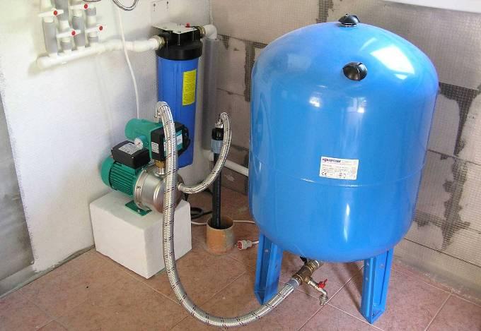
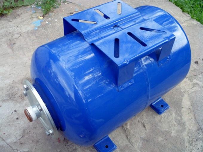
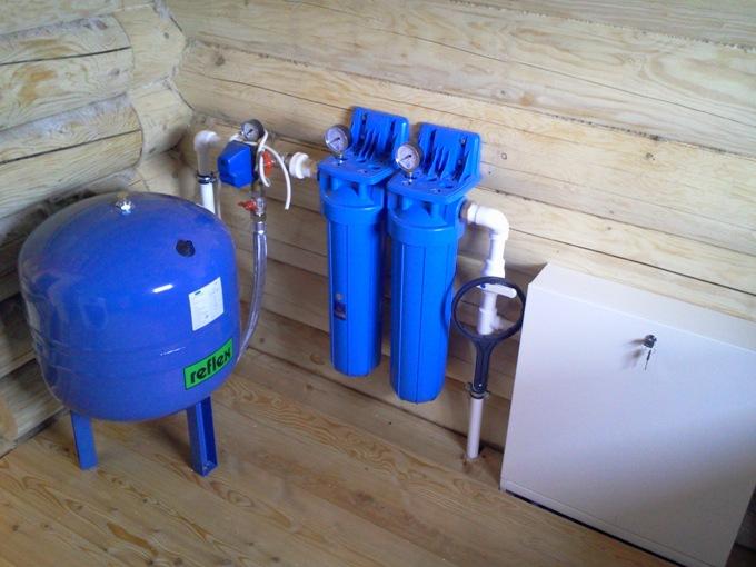
The hydraulic accumulator is a special metal sealed container containing inside an elastic membrane and a certain amount of water under a certain pressure.
A hydraulic accumulator (in other words, a membrane tank, a hydraulic tank) is used to maintain stable pressure in the water supply system, protects the water pump from premature wear due to frequent switching on, and protects the water supply system from possible water hammer. When you turn off the voltage, thanks to the accumulator, you will always be with a small supply of water.
Figure 13 shows a diagram in which steam under boiler pressure is required, as well as steam with lower pressure. Some process applications cannot carry low pressure steam, and steam may be required at any time during boiler pressure. If the peak load is caused by high pressure consumers, the pressure maintenance valve in Figure 13 will sense a pressure drop and modulate to its place, thereby preserving high pressure steam for high pressure users, leaving a steam accumulator to supply low pressure demand during this period.
Here are the main functions that the accumulator performs in the water supply system:
- Protecting the pump from premature wear. Due to the supply of water in the membrane tank, when the tap is opened, the pump will only turn on if the supply of water in the tank runs out. Any pump has a certain rate of inclusions per hour, therefore, due to the accumulator, the pump will have a stock of unused inclusions, which will increase its life.
- Maintaining constant pressure in the water supply system, protection against drops in water pressure. Due to differences in pressure with the simultaneous inclusion of several taps, sharp fluctuations in water temperature occur, for example, in the shower and in the kitchen. The accumulator successfully copes with such unpleasant situations.
- Protection against water hammer, which can occur when the pump is turned on, and can spoil the pipeline in order.
- Maintaining a supply of water in the system, which allows you to use water even during a power outage, which in our time happens quite often. This feature is especially valuable in country houses.
Accumulator device
Thus, the system delivers an alternating low-pressure load through a steam accumulator, and the maximum possible flow rate for a high-pressure load is provided by the action of a pressure-maintaining valve. In Figure 14, the boiler is processed at normal design pressure, for example 10 bar, and the steam passes to alternating loads that require no more than, for example, 5 bar.
Practical considerations for steam batteries
This draws steam out of the steam accumulator and over time the vapor pressure of the accumulator drops. Valve B responds to downstream pressure in the distribution line, which also acts as a pressure reducing valve. Then the steam enters the steam accumulator, which is recharged to the maximum pressure, slightly lower than the boiler pressure. At any plant, the design engineer should strive to provide at least the minimum service in the event that the steam battery and related equipment either require maintenance or break down.
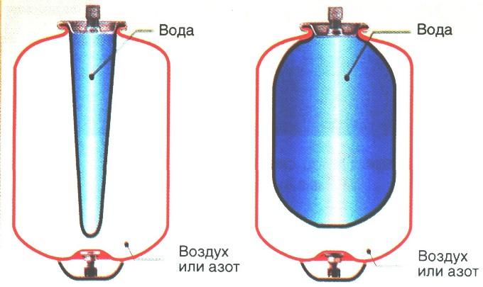
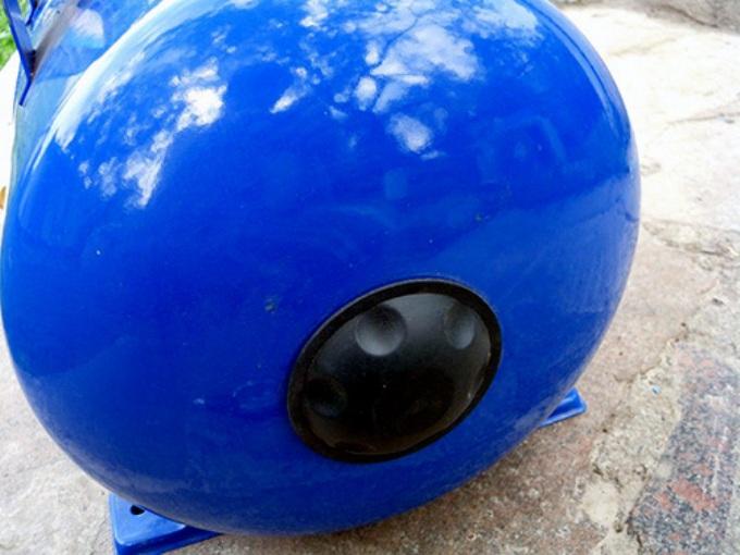
The sealed housing of this device is divided by a special membrane into two chambers, one of which is designed for water, and the other for air.
Water does not come into contact with the metal surfaces of the body, as it is located in a water chamber-membrane made of strong butyl rubber material that is resistant to bacteria and meets all hygiene and sanitary standards for drinking water.
This will include ensuring adequate and safe isolation of the battery with valves and, possibly, some means of protecting the boiler from overload if large changes in demand cannot be avoided. The most obvious solution here is a backup pressure maintenance valve.
Effect on the burning rate of the boiler
The steam accumulator and pressure maintenance valve together protect the boiler from overloads and allow the boiler to work properly until it is rated. This is important to achieve good efficiency and at the same time to deliver clean, dry, saturated steam. Figures 16 and 17 show the firing speed without a steam accumulator and the firing speed with a steam accumulator, respectively.
In the air chamber is a pneumatic valve, the purpose of which is to regulate the pressure. Water enters the accumulator through a special connecting pipe on the thread.
The accumulator device must be mounted in such a way that it can be easily disassembled in case of repair or maintenance, without draining all the water from the system.
What should be the air pressure in the air cavity of the accumulator?
With proper design and operation, steam from a steam accumulator is always clean and has a dry fraction close enough to a steam accumulator, designed with a large surface of water and sufficient steam space to produce high-quality steam almost instantly during peak demand periods. In the case of some vertical steam accumulators, the vapor space increases to compensate for the smaller surface of the water.
Steam batteries are sometimes used to provide clean steam if the steam is in direct contact with the product; as in stationary and industrial sterilizers, textile finishes and some applications in the food industry and the beverage industry.
The diameters of the connecting pipe and the discharge pipe should match, if possible, then this will avoid undesirable hydraulic losses in the system pipeline.
In the membranes of hydraulic accumulators with a volume of more than 100 l there is a special valve for bleeding air released from water. For small-sized accumulators in which there is no such valve, a device for bleeding air, for example, a tee or a tap, which closes the main line of the water supply system, must be provided in the water supply system.
After the battery is filled with water, and under normal operating conditions, the addition of water and the overflow rate are very small. If superheated steam is used, the amount of added water will be related to the amount of superheat, but since the specific heat of superheated steam is lower than water, it will have less impact on changes in water level.
Features of the device of modern hydraulic tanks
If saturated steam is used, the increase in water level simply depends on the heat loss from the vessel. With proper insulation, heat loss is minimal, so an increase in water level and, therefore, overflow through a steam trap are also minimal.
In the accumulator air valve, the pressure should be 1.5-2 atm.
The principle of operation of the accumulator
The accumulator works like this. The pump delivers pressurized water to the pressure accumulator membrane. When the pressure threshold is reached, the relay switches off the pump and water stops flowing. After the pressure starts to drop during the intake of water, the pump switches on again automatically and supplies water to the accumulator membrane. The larger the volume of the tank, the more effective the result of its work. The operation of the pressure switch can be adjusted.
Classification of accumulators for water supply systems
The steam accumulators described and illustrated in this Module were large and horizontal. Steam batteries are always designed and manufactured in accordance with the application, and vessels with a diameter of only 1 m are not uncommon. Also, for small batteries, steam is usually vertical. Any configuration can support the same storage and discharge speeds, and it can be easier to find a place for a vertical unit.
This is usually the most expensive part of a steam battery system and will be individually designed for each application. For industrial installations, this usually ranges from 5 to 30 bar, although power plants can be rated at 150 bar. Typically, the ratio of diameter to total length is from 4 to 6, but this can vary significantly depending on the conditions of the site.
During operation of the accumulator, air dissolved in water gradually accumulates in the membrane, which leads to a decrease in the efficiency of the device. Therefore, it is necessary to prevent accumulator, bleeding the accumulated air. The frequency of preventive measures depends on the volume of the tank and the frequency of its operation, which is approximately once every 1-3 months.
Steam accumulators usually have a cylindrical shape with elliptical ends, as this is structurally the most efficient form. They will be made from the stove of the boiler. The higher the permissible pressure difference between the boiler pressure and the pressure in the installation, the greater the proportion of vaporized vapor and, therefore, the lower the consumed steam power.
In addition to a real-time storage tank, a vessel must have. Sufficient water in the lower part of the vessel under minimum conditions for placement and closure of steam injectors. Adequate clearance above water under fully charged conditions to provide a reasonable surface area for the release of steam. This is important because the instantaneous steam release rate can be the ultimate criterion if peak loads are heavy and harsh.
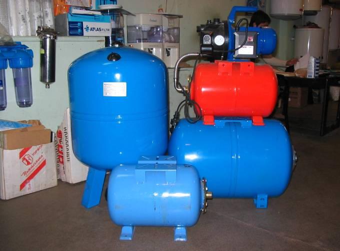
These devices can be of vertical and horizontal configuration.
The principle of operation of the devices has no differences, except that the vertical accumulators with a volume of more than 50 l in the upper part have a special valve for bleeding air, which gradually accumulates in the water supply system during operation. Air accumulates in the upper part of the device, because the location of the valve for bleeding is selected in the upper part.
Battery Rationale
There are several ways in which the capital costs of installing a battery can be justified, and they will often be paid in a short amount of time. The following points should be considered during the initial analysis. Compare installation costs for a boiler-only installation to meet maximum demand, as well as the smaller boiler used with the battery.
Estimate fuel economy as a smaller boiler works closer to its maximum power and more stable load. In a recent case study, a brewery calculated 10% fuel economy and a payback period of about 18 months.
In horizontal devices for bleeding air, a special tap or drain is installed, which is installed behind the accumulator.
Of devices of small sizes, regardless of whether they are vertical or horizontal, air is vented by completely draining the water.
Choosing the shape of the tank, proceed from the size of the technical room where they will be installed. It all depends on the dimensions of the device: which one fits better in the space allotted for it, this will be installed, regardless of whether it is horizontal or vertical.
As a result of the alignment of the peaks and troughs of vaporization, determine whether the specific cost of fuel is less. Then you can agree to reduce the maximum supply rate. Evaluate the financial benefits of lowering the cost of boiler rooms, steam valves and steam equipment. These advantages will be achieved due to a higher load on the boiler and better steam.
Steam batteries are not old-fashioned relics of the past. Steam batteries have been installed throughout modern industry, including biotechnology, stationary and industrial sterilization, product testing facilities, the production of printed and food products, as well as more traditional industries such as breweries and trading floors.
The accumulator connection diagram
Depending on the assigned functions, the connection diagram of the accumulator to the water supply system may be different. The most popular accumulator connection diagrams are given below.
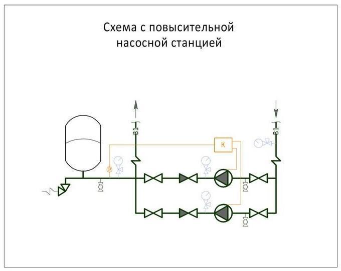
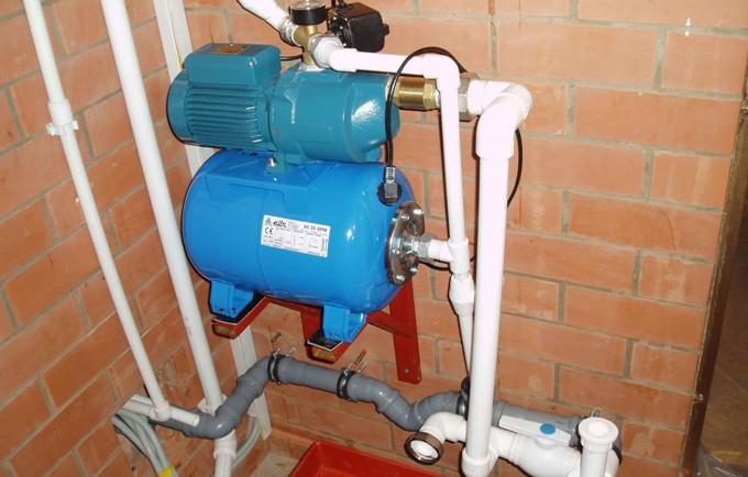
Such pumping stations are installed where there is a large water consumption. As a rule, one of the pumps at such stations operates continuously.
At the booster pump station, the accumulator serves to reduce pressure surges during the switching on of additional pumps and to compensate for small bumps.
Modern boilers have become smaller, and the use of small water tube boilers, coil boilers and ring boilers has increased, all of which are effective, but which reduce the thermal power of the system and make it vulnerable to maximum load problems.
There are many more applications for steam batteries. For the long-term peaks that the boiler plant should ultimately process, the steam accumulator can be used to store, for example, 5 minutes of peak flow, which ensures a sufficient service life of the boiler plant. Steam accumulators can also be used with boilers with electrodes or immersion heaters, so that steam can be generated with a peak, stored and used during peak loads.
Another such scheme is widely used when a frequent interruption in the supply of electricity to booster pumps occurs in the water supply system, and the presence of water is vital. Then the water supply in the accumulator saves the situation, playing the role of a backup source for this period.
The larger and more powerful the pumping station, and the greater the pressure it must maintain, the greater the volume of the hydraulic accumulator, which acts as a damper, should be.
The buffer capacity of the hydraulic tank also depends on the volume of the required water supply, and on the difference in pressure when the pump is turned on and off.
The possibilities are endless. Thus, a steam accumulator is an effective tool, since it can provide the most economical way to supply steam to a batch process. Unloading pump pump with battery. Sounds like a snake that smells like she didn't like it. It also looks like a James Bond gadget.
When this pressure reaches the valve setting, it moves and unloads, redirects or destroys the pump. This check valve is capable of handling a pump of up to 15 gallons per minute. It can be used in conjunction with any size check for larger systems.
For long and trouble-free operation, the submersible pump must make from 5 to 20 starts per hour, which is indicated in its technical characteristics.
When the pressure in the water supply system drops to the minimum value, the pressure switch automatically turns on, and at the maximum value, it turns off. Even the smallest water flow rate, especially in small water supply systems, can reduce the pressure to a minimum, which will instantly give a command to turn on the pump, because the water leak is compensated by the pump instantly, and after a few seconds, when replenishing the water supply, the relay will turn off the pump. Thus, with minimal water consumption, the pump will work almost idle. This mode of operation adversely affects the operation of the pump and can quickly disable it. The position can be corrected by a hydraulic accumulator, which always has the required supply of water and successfully compensates for its insignificant consumption, and also protects the pump from frequent switching on.
Application issues outweigh the benefits. There are design aspects that make it superb. He is probably not immune to siltation. The area that would be silt is very small in relation to the valve labor. Ultimately, the seat expands until the system dies. This product is not easy to manufacture.
Concentricity is critical, diameters must be maintained, and surface finish is very important. However, if we do not make the valve correctly, it will not pass the test. You should pay attention to the details in the design of circuits and manifolds. Attention to detail is a phrase that is very important for the successful application of this valve. Attention to detail is what Rick put into this valve. Diameters, weights, strokes, gains, timings. When it is assumed that the valve operates with a 15% difference, attention to detail is what made it work.
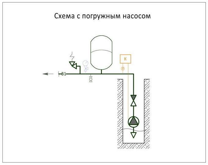
In addition, the accumulator, connected to the circuit, smooths out a sharp increase in pressure in the system when the submersible pump is turned on.
The volume of the hydraulic tank is selected depending on the frequency of switching on and the power of the pump, water flow per hour and the height of its installation.
Rick drew attention to the details in the valve, but you need to pay attention to the details in the design of the circuit, as well as the design of the manifold. The valve opens at 600 psi and is vented at 510 psi. Every drop in pressure is against you.
Everything distracts from the differential used. I was taught not to use the word in composition, as it is considered confrontational.
- Pump malfunction.
- Inability to return the pump back to line.
- Disruption during reset.
- Violent, endless fluctuations between discharge and discharge.
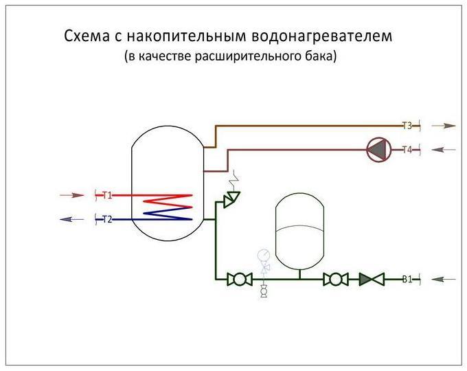
For the storage water heater in the connection diagram, the accumulator plays the role of an expansion tank. When heated, the water expands, increasing the volume in the water supply system, and since it does not have the ability to compress, the smallest increase in volume in a confined space increases pressure and can lead to the destruction of water heater elements. Here, too, a hydraulic tank will come to the rescue. Its volume will directly depend on and increase from an increase in the volume of water in the water heater, an increase in the temperature of the heated water and an increase in the maximum allowable pressure in the water supply system.
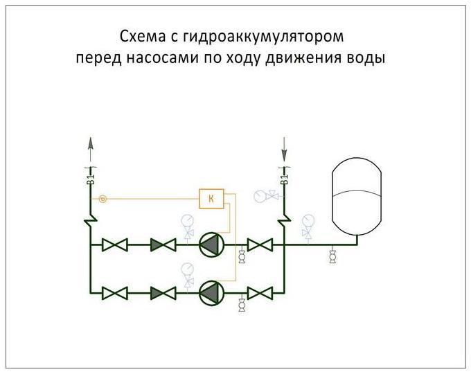
The hydraulic accumulator is connected before the booster pump along the water. It is needed to protect against a sharp decrease in pressure in the water supply network when the pump is turned on.
The capacity of the accumulator for the pumping station will be the greater, the more water is used in the water supply system and the smaller the difference between the upper and lower pressure scales in the water supply in front of the pump.
How to install a hydraulic accumulator?
From the foregoing, it can be understood that the device of the accumulator is absolutely not like an ordinary water tank. This device is constantly in operation, the membrane is constantly in dynamics. Therefore, the installation of the accumulator is not so simple. The tank must be strengthened during installation reliably, with a margin of safety, noise and vibration. Therefore, the tank is fixed to the floor through rubber gaskets, and to the pipeline through rubber flexible adapters. You need to know that at the inlet of the hydraulic system, the supply section should not be narrowed. And one more important detail: for the first time, the tank must be filled very carefully and slowly, using a weak pressure of water, in case the rubber bulb has stuck from a long period of inactivity, and with a sharp pressure of water it can be damaged. It is best to remove all air from the pear before putting it into operation.
The accumulator must be mounted so that during operation it can be freely approached. It is better to entrust this task to experienced specialists, since very often the tank breaks down due to some unaccounted for, but important trifle, for example, due to the mismatch of the pipe diameter, unregulated pressure, etc. It is impossible to conduct experiments here, because the normal operation of the water supply system is at stake.
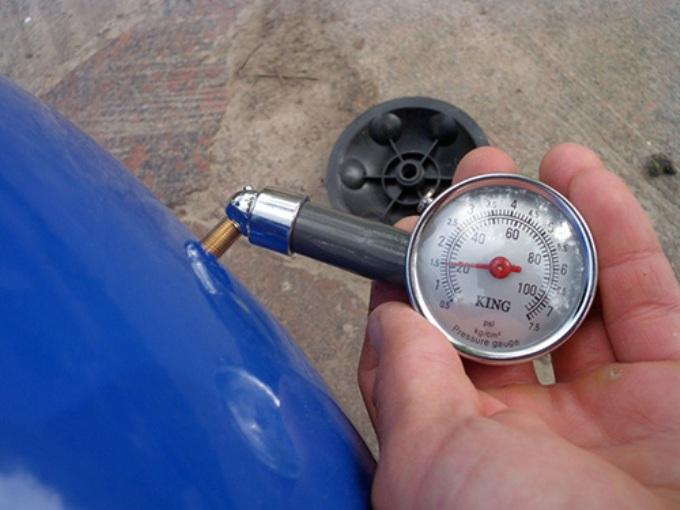
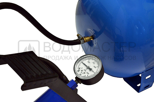
So you brought a purchased tank to the house. What to do next with it? It is immediately necessary to find out the pressure level inside the tank. Typically, the manufacturer pumps it up to 1.5 atm, but there are times when, due to a leak, indicators are reduced by the time of sale. To make sure that the indicator is correct, you need to unscrew the decorative cap on an ordinary automobile spool and check the pressure.
How to check it? Usually a manometer is used for this. It can be electronic, mechanical automobile (with a metal case) and plastic, which comes with some models of pumps. It is important that the pressure gauge has greater accuracy, since even 0.5 atm changes the quality of the hydraulic tank, so it is better not to use plastic pressure gauges, since they give a very large error in performance. These are usually Chinese models in a weak plastic case. The indicators of electronic pressure gauges are affected by the battery charge and temperature, in addition, they are very expensive. Therefore, the best option is an ordinary automobile pressure gauge that has passed the test. The scale should be on a small number of divisions, in order to be able to more accurately measure pressure. If the scale is designed for 20 atm, and you need to measure only 1-2 atm, then you can not expect high accuracy.
If there is less air in the tank, then there is a larger supply of water, but the pressure difference between an empty and an almost full tank will be very significant. It's all about preferences. If it is necessary that the water supply constantly has a high water pressure, then the tank should have a pressure of at least 1.5 atm. And for domestic needs, 1 atm may well be enough.
At a pressure of 1.5 atm, the hydraulic tank has a smaller supply of water, because of which the booster pump will turn on more often, and in the absence of light, the supply of water in the tank may simply not be enough. In the second case, you will have to sacrifice pressure, because you can take a shower with a massage when the tank is full, and as it is empty, only the bath.
When you decide what is more important for you, you can set the desired mode of operation, that is, either pump air into the tank or bleed excess.
It is undesirable to lower the pressure below 1 atm, as well as excessively exceed it. A pear filled with water at insufficient pressure will touch the walls of the tank, and can quickly become unusable. And excessive pressure will not allow to pump a sufficient amount of water, since most of the tank will be occupied by air.
Pressure switch setting
You also need to configure the pressure switch. Opening the cover, you will see two nuts and two springs: large (P) and small (delta P). With their help, you can adjust the maximum and minimum pressure levels at which the pump turns on and off. A large spring is responsible for turning on the pump and pressure. By design, you can see that it, as it were, promotes water to close the contacts.
![]()
Using a small spring, the pressure difference is set, as stipulated in all instructions. But the instructions do not indicate a reference point. It turns out that the reference point is the spring nut P, \u200b\u200bthat is, the lower limit. The lower spring, which is responsible for the pressure difference, resisting the pressure of water, pushes the movable plate from the contacts.
When the correct air pressure has already been set, the accumulator can be connected to the system. By connecting it, you need to carefully monitor the manometer. All accumulators show the normal and maximum pressure values, the excess of which is unacceptable. Manual disconnection of the pump from the network occurs when the normal accumulator pressure is reached, when the limit value of the pump head is reached. This happens when the pressure increase stops.
The pump capacity is usually not enough to pump the tank to the limit, but this is not even particularly necessary, because pumping reduces the life of the pump and pear. Most often, the pressure limit for disconnection is set at 1-2 atm higher than inclusion.
For example, when the pressure gauge is 3 atm, which is enough for the needs of the owner of the pumping station, you need to turn off the pump and slowly turn the small spring nut (delta P) to decrease, until the mechanism triggers. After that, you need to open the tap and drain the water from the system. Observing the pressure gauge, it is necessary to note the value at which the relay turns on - this is the lower pressure limit when the pump turns on. This indicator should be slightly higher than the pressure indicator in an empty accumulator (by 0.1-0.3 atm). This will make it possible to serve a pear for a longer period of time.
When the nut of the large spring P is rotated, a lower limit is set. To do this, turn on the pump in the network and wait until the pressure reaches the desired level. After that, it is necessary to adjust the nut of the small spring "Delta P" and finish the adjustment of the accumulator.
In the air chamber of the accumulator, the pressure should be 10% lower than the pressure when the pump is turned on.
An exact indicator of air pressure can be measured only when the tank is disconnected from the water supply system, in the absence of water pressure. Air pressure must be constantly monitored, adjusted as necessary, which will add to the membrane lifespan. Also, in order to continue the normal functioning of the membrane, a large pressure drop must not be allowed when the pump turns on and off. A difference of 1.0-1.5 atm is normal. Stronger pressure drops reduce the life of the membrane, stretching it greatly, in addition, such pressure drops do not allow comfortable use of water.
Hydraulic accumulators can be installed in places with low humidity, not subject to flooding, so that the flange of the device can serve successfully for many years.
When choosing a brand of a hydraulic accumulator, it is necessary to pay special attention to the quality of the material the membrane is made of, check certificates and sanitary-hygienic conclusions, making sure that the hydraulic tank is designed for systems with drinking water. You also need to make sure there are spare flanges and membranes that should be included, so that in case of a problem you do not have to buy a new hydraulic tank.
The maximum pressure of the accumulator for which it is designed must not be less than the maximum pressure in the water supply system. Therefore, most devices withstand a pressure of 10 atm.
To determine how much water can be used from the accumulator when the electricity is turned off, when the pump stops pumping water from the water supply system, you can use the table for filling the membrane tank. The water supply will depend on the setting of the pressure switch. The higher the pressure difference when turning the pump on and off, the greater the supply of water will be in the accumulator. But this difference is limited for the reasons stated above. Consider the table.
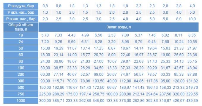
Here we see that in the membrane tank with a volume of 200 l when the pressure switch is set, when the pump on indicator is 1.5 bar, the pump off is 3.0 bar, the air pressure is 1.3 bar, the water supply will be only 69 l, which is approximately one third of the total tank volume .
Calculation of the required volume of the accumulator
To perform the calculation of the accumulator, use the following formula:
Vt \u003d K * A max * ((Pmax + 1) * (Pmin + 1)) / (Pmax - Pmin) * (P + 1),
- Amax - maximum consumption of liters of water per minute;
- K is a coefficient that depends on the power of the pump motor;
- Pmax - pressure when the pump is turned off, bar;
- Pmin - pressure when turning on the pump, bar;
- Rd. - air pressure in the accumulator, bar.
As an example, we select the necessary minimum accumulator volume for the water supply system, taking, for example, the Aquarius BTsPE 0.5-40 U pump with the following parameters:
| Pmax (bar) | Pmin (bar) | Bar (bar) | A max (cubic m / hour) | K (coefficient) |
| 3.0 | 1.8 | 1.6 | 2.1 | 0.25 |
Using the formula, we calculate the minimum volume of HA, which is 31.41 liters.
Therefore, we choose the next closest GA size, which is 35 liters.
The tank volume in the range of 25-50 liters is ideally consistent with all the methods for calculating the volume of HAs for domestic water systems, as well as with the empirical designations of different manufacturers of pumping equipment.
With frequent power outages, it is advisable to choose a larger tank, but at the same time it should be remembered that water can fill the tank only 1/3 of the total volume. The more powerful the pump is installed in the system, the greater should be the volume of the accumulator. This conformity of dimensions will reduce the number of short starts of the pump and extend the life of its electric motor.
If you bought a large accumulator, you need to know that if you do not use water regularly, it stagnates in the tank and its quality deteriorates. Therefore, choosing a hydraulic tank in the store, you need to consider the maximum amount of water used in the house's water supply system. Indeed, with a small flow of water, it is much more expedient to use a tank with a volume of 25-50 liters than 100-200 liters, in which water will be wasted in vain.
Accumulator repair and prevention
Even the simplest hydraulic tanks require attention and care, like any working and beneficial device.
Reasons for repairing the accumulator are different. This is corrosion, dents in the housing, a violation of the integrity of the membrane or a violation of the tightness of the tank. There are also many other reasons that oblige the owner to repair the hydraulic tank. In order to prevent serious damage, it is necessary to regularly inspect the surface of the accumulator, monitor its work to prevent possible problems. It is not enough to inspect the GA twice a year, as stipulated in the instructions. After all, one malfunction can be eliminated today, and tomorrow you can not pay attention to another problem that has arisen, which within six months will turn into an irreparable and can lead to failure of the hydraulic tank. Therefore, the accumulator must be inspected at every opportunity so as not to miss the slightest malfunctions, and to repair them in time.
Causes of breakdowns and their elimination
![]()
The cause of the breakdown of the expansion tank may be too frequent on-off of the pump, water outlet through the valve, weak water pressure, weak air pressure (lower than calculated), weak water pressure after the pump.
How to fix the malfunction of the accumulator with your own hands? The reason for the repair of the accumulator can be weak air pressure or its absence in the membrane tank, damage to the membrane, damage to the housing, a big difference in pressure when the pump is turned on and off, incorrectly selected tank volume.
You can troubleshoot as follows:
- to increase the air pressure, it is necessary to pump it through the tank nipple with a garage pump or compressor;
- a damaged membrane can be repaired at a service center;
- a damaged case and its tightness is also eliminated in the service center;
- it is possible to correct the difference in pressure by setting the differential too large in accordance with the frequency of switching on the pump;
- the adequacy of the tank volume must be determined before it is installed in the system.
In a pressure accumulator with a replaceable membrane, pressure air is pumped between the walls of the housing and the membrane. This air pressure should have a very definite value, be regularly monitored and, if necessary, regulated.
In this article, we will deal with the factory and operating air pressure in the accumulator and consider how, when, and how it needs to be regulated.
Pressure accumulator
Those who already have a good idea of \u200b\u200bthe accumulator device know that inside the membrane there is water under pressure, and outside the membrane air is pumped.
The water pressure inside the membrane is created by the pump and only by the pump, and with the help of a pressure switch or automation units, a pressure range (P on and P off) is set in which the entire water supply system operates.
The maximum water pressure for which the accumulator is designed is indicated on its nameplate. As a rule, this pressure is 10 bar, which is quite enough for any domestic water supply system. The water pressure in the accumulator depends on the hydraulic characteristics of the pump and the settings of the system, but the air pressure between the membrane and the housing is a characteristic of the accumulator itself.
Factory air pressure:
Each accumulator comes from the factory with preliminary air injection. As an example, we give the values \u200b\u200bof factory air injection for accumulators of the Italian company Aquasystem:
The actual value of the pre-charge pressure is also indicated on the label of the accumulator (pre-charge pressure).
So what exactly should the air pressure be in the accumulator?
For water systems with pressure switches:
The pressure in the accumulator must be 10% lower than the pressure on the pump.
The fulfillment of this requirement guarantees the presence of a minimum residual water in the accumulator at the time of switching on the pump, ensuring a continuous flow.
For example, if the pump starts at 1.6 bar, the air pressure in the accumulator should be about 1.4 bar. If the pump starts at 3 bar, the air pressure should be around 2.7 bar.
For water supply systems with a frequency converter:
The pressure in the accumulator must be 30% lower than the constant pressure maintained by the frequency converter.
It turns out that the pressure of the factory air injection is not universal for all systems, because the pressure on the pump can be individually controlled by the user and the tank manufacturer can not predict it. Therefore, air pressure must be adjusted in each specific system in accordance with the above recommendations.
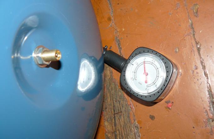
Methods of monitoring and adjusting the air pressure in the accumulator
Air pressure can be checked and inflated with a standard automobile pump or compressor, connecting it to the nipple, which is usually located under the plastic protective cap.
The larger the tank, the longer it takes to pump it up. For accumulators with a volume of 50 liters or more, we strongly recommend using a compressor.
When changing (increasing or decreasing) the pressure on the pump, do not forget to also change the air pressure in the accumulator. And do not confuse this procedure with the setting of a pressure switch.
Over time, the pressure in the air cavity of the accumulator may decrease, so it is recommended to check it regularly.
Air Pressure Monitoring Intervals:
- If you use a water system only in the warm seasonthen control is recommended before the start of each new season.
- If you use the water supply system year-round, it is recommended to check 2-3 times a year.
You can treat this simple procedure as a planned tech. a service that is very likely to extend the life of the membrane.
If you notice any oddities in the operation of the water supply system, it makes sense to make an unscheduled control of the air pressure in the hydraulic tank, as well as the pressure on and off the pump (controlled by a water pressure gauge).
By the way, the stability of air pressure in the accumulator over a long time is one of the important indicators of its quality.