Rotary pump. Rotary pumps: vane, vacuum, barrel. Modern wet and dry rotor pumps.
If in the case of the choice of the pump the question arose, which is better - a pump with a wet rotor or with a dry one, then we will try to deal with such units using the example of circulation pumps. It is known that such equipment is successfully used to create excellent and uninterrupted coolant circulation in the heating system of a private house.
Both provide reduced power consumption during operation - when flow and pressure are needed to operate. They also keep power in standby mode - when the system is idling or idle. In addition, they can reduce the required size - and, consequently, the cost of valves, conductors and filters required for the circuit.
The load gear pump shown in fig. 19, minimizes energy consumption during operation by dividing the total discharge flow in accordance with the remote pressure of the primary function and the main stream. This is achieved by a single load measurement signal originating from the priority circuit and is routed as close as possible to the discharge side of the pump gears.
In working condition, a pump with any type of rotor pumps the volume of fluid through the pipes, forcing it to move constantly forward. As a result of this effect on the coolant, we have the following advantages:
- Constant temperature indicator of radiators in all areas of the heat supply system;
- The absence of air jams in the system, and therefore, the exclusion of the probability of water hammer in it;
- Saving family funds for fuel or electricity consumption for heating the coolant (now you do not need to stiffen the boiler intensively so that the desired water temperature most likely reaches the radiators in the back room of the house and warms it). Pumps with a wet rotor or a dry rotor will make everything faster and more productive.
Important: pumps with rotors of all types have two openings in their design: suction and discharge. Thus, the unit performs its work, promoting it in a closed loop.
Adding discharge control to the pump circuit, fig. 20, allows the system to save energy in standby mode, as well as in operating mode. This control should be installed in parallel with the inlet of the hydrostat and as close as possible to the discharge side of the gears. It must be piloted with the same load measurement signal as in the figure. This signal causes the pump to pump out the entire flow from the outlet to the secondary circuit and at a pressure significantly higher than the hydrostat pressure setting in standby mode.
How is such an assembly?
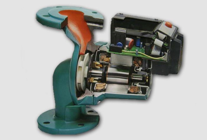
Circulation pumps have a device similar to drainage pumps. A pump housing with a dry or wet rotor is most often made of durable alloys such as brass, cast iron, stainless steel or bronze. Such metals interact well with high temperature water or with aggressive media (in the case of a drainage rotor).
The unloader control must operate with the same remote load detection signal that controls the hydrostat. Unlike a hydrostat, the unloading bucket of the unloading device is designed with opposite sections having a ratio of at least 2: any given line pressure that exceeds 50% of the pump discharge pressure will close the discharge control. The ability of the discharge control to unload the pump to atmospheric pressure is controlled by the force of a Belleville or plunger spring.
The rotor itself produces either durable stainless steel or ceramic. And the working unit (wheel with blades) is located on the rotor shaft.
The principle of operation of such a device is to create a centrifugal force inside the pump and looks like this:
In the on state, the rotor drives a wheel with an impeller, which rotates fast enough, creating a decrease in pressure in the pump chamber. This contributes to the flow of water into the tank. Then, the water entering the chamber increases the pressure and at the same time is pressed against the walls of the internal tank of the pump. Due to this difference, water is pushed into the outlet. The cycle repeats over and over until the unit shuts down.
The discharge control is set to the lowest value to maintain the internal pressure load of the gear pump. Compared to the standard gear pump circuit with a fixed displacement, this control can reduce standby power consumption by 90%.
This leads to the fact that the hydrostat and the discharge control of the load-sensitive gear pump respond to a conditional signal in accordance with the discharge pressure. This is achieved by providing lightweight travel, fig. 21, which causes the hydrostat to act as the main stage of the pilot control valve.
Division of pumps with a rotor into types
All pumping equipment with a rotor can be divided into two types:
- Units with a "wet" rotor;
- Pumps with a "dry" rotor.
In the first case, we are talking about a mechanism whose rotor does not have direct contact with the pumped water. Separation of the rotor in the pump mechanism is supported by special ceramic or metal seals in the form of rings. They protect the rotor from direct contact of the nodes with the pumped medium. But here the principle of operation of the device with a wet rotor is that between the protective rings rubbing against each other there is a thin, barely noticeable water layer. It helps to maintain the pressure difference in the heating system and in the working chamber, and therefore, ensures the tightness of the rotor compartment. Moreover, at the moments of operation of the ring, the seals rub against each other more strongly, which ensures even greater tightness of the device.
The ability to install a load measurement line is patented and makes the load-sensitive gear pump useful for functions other than load sensitivity. Combined control and measuring gear pump, fig. 22, is designed for large volume pumps and bypasses secondary flow into the tank. It is also patented and can be used in the same applications as the dual-control pump. However, since the secondary stream must be directed into the tank, it cannot be used when the secondary circuit controls the load.
Important: circulation units for heating or air conditioning systems with a wet rotor can be either single-phase or three-phase. That is, you can use such pumps at home, and at a large production or industrial enterprise.
Thanks to just such operating principles, a wet rotor unit has a number of advantages:
Rotary vane oil pumps are the primary pumps on most vacuum systems used in the heat treatment industry. They are also called “reference” pumps when used in combination with a booster pump or with an amplifier and secondary pump, usually with a diffusion style. A rotary vane pump can also be used separately when high vacuum is not required and lower pumping is acceptable.
There are two-stage designs that use two rotors built into the pump inside the pump. Due to the predominance of rotary vane pumps, it is important that designers and users of industrial vacuum equipment have a good understanding of how these pumps work. This series of articles will cover how the pump works, pump designs, pump oils, single-stage and two-stage pump designs, pollution and gas ballast, general accessories, applications, troubleshooting, and pump maintenance.
- Low noise when pumping water through the system;
- Modest weight and small dimensions;
- Possibility of long-term operation without stops;
- Economical power consumption;
- Easy installation, configuration, maintenance and repair.
Moreover, monoblock devices with a “wet” rotor are more popular among the modern consumer.
Of the various vacuum pump technologies, rotary vane pumps are considered wet, forced displacement pumps. They are often called “wet” pumps because the injected gas is exposed to the oil used as a lubricant to provide a seal.
For this reason, the oil is carefully selected and specially designed for use. A positive offset indicates that the pump is operating by mechanically capturing the volume of gas and moving it through the pump, creating a low level. Inlet pressure.
Important: but along with all these advantages, the efficiency of a pump with a wet rotor is significantly lower and amounts to about 55%. Thus, it is best to use such a mechanism in houses with a small area, where the closed loop of the heating system has a small length.
If we talk about water-supply pumps with a “wet” type rotor, then here the devices will be slightly inferior to their counterparts with a “dry” rotor. But this applies only to surface aggregates.
Advantages and disadvantages of rotary pumps
Rotary vane pumps are designed so that the pump stator is immersed in oil and contains a rotor that is eccentrically mounted. The rotor contains two blades that slide in diametrically opposite slots. The blades can be spring-loaded, but otherwise rely on centrifugal force to push outward to the stator wall. When the rotor rotates, the ends of the blades are constantly in contact with the stator wall.
The entire assembly is machined and mounted with tight tolerances, so that the gap between the upper part of the rotor and the stator wall is approximately 0.25 mm. With oil, providing a seal between the inlet and outlet sides. The oil circulates from the oil reservoir to the inside of the pump and is discharged through the exhaust valve using the pumped gas.
Important: a prerequisite for the high-quality operation of the pump with a wet rotor and compliance with the principles of pumping water is the correct installation of the unit on the circuit. Here, the equipment shaft should be located strictly horizontally relative to the closed loop of the heating system. Only in this case, a high-quality liquid supply to the bearings for lubricating the working units will be ensured through the sleeve.
If the pressure drops exceed this, a back leak through the seal will occur, which is one of the limitations. factors in the final vacuum achieved by rotary vane pumps. A typical rotary vane pump has four stages of operation.
The volume occupied by the gas increases due to the crescent-shaped space created by the rotor mounted on the offset. The upper large blade passes through the inlet, sealing it from the injected gas. Compression. Further rotation compresses and heats the gas in front of the lowest blade, reducing its volume due to a decrease in the space between the rotor and the stator. Exhaust When the lower blade continues to rotate, the pressure in front of it increases enough to open the exhaust valve, discharging gas at a pressure slightly above atmospheric.
One of the most important components in a rotary vane pump is the exhaust valve, which is powered by several ports.
- The first rotation of the rotor through 180 ° causes the gas to flow into the pump chamber.
- The gas pressure decreases in proportion to the increase in its volume.
- This draws gas into the pump and generates the necessary vacuum.
- Insulation.
Dry Rotor Pumps
For all their productive capacity, units of this type differ in a number of disadvantages:
- High noise level in working condition.
- The need for continuous monitoring of the quality of the processed medium, since pumps with a "dry" rotor do not tolerate the presence of impurities in the water or air molecules. Such "neighbors" are able to violate the tightness of the seal rings in the mechanism.
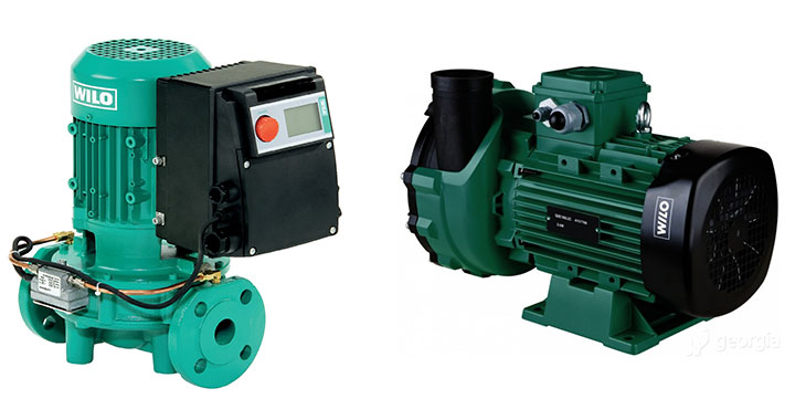
Moreover, the entire range of pumps with a “dry” rotor is divided into three types:
General description of rotary pumps
A metal base plate limits the movement of the elastomeric part of the valve. Some valves are metal without an elastomer, but this design is susceptible to the effect known as “suction” if the pump stops under vacuum. Since the valve does not use an elastomer, oil can seep past it and “suck” back through the pump and into the vacuum chamber or furnace. Since the valve opens and closes at every turn, it is a source of noise and is susceptible to wear, whether the elastomer is used or not.
- Block devices;
- Vertical unitsin which the engine is in a vertical position, and both nozzles are located on the same axis;
- Cantilever (horizontal)in which the engine is mounted horizontally, and the nozzles are perpendicular to each other.
Rules for choosing a pump: “dry” or “wet” rotor
Rotary pumps type M
The valve operates mechanically and is forced to open by the pressure created by the pump, and then closes by atmospheric pressure. Rotary pumps are lubricated with oil, which not only provides a seal between the high and low pressure sides of the pump, but also lubricates the pump bearings and other rotating components. Some pump designs, especially older ones that use lubricating oil circulation, were based on a vacuum supply system, thanks to which the vacuum created by the pump itself was also used to lubricate the lubricating oil through the rotor bearings.
In order for the heating system to work as efficiently as possible, it is necessary to choose the right pump in accordance with the parameters of the house and the characteristics of the heating system. Only in this case and subject to proper installation of the mechanism in compliance with the principles of its operation, the heat in the house will be of high quality and long-lasting.
Other pumps use spring seals with a spring seal around the rotor shaft. This is a dynamic type seal that also requires lubrication. Although the distribution of the oil filter is still in use, more modern pumps use a separate oil pump to circulate the oil through the passages machined into the stator, to the bearings and rotor seals. When the vacuum pump is running, its rotation also rotates the oil pump, which is mounted on the same shaft, and creates a positive oil supply pressure 4 bar above atmospheric pressure.
So, when choosing a pump, consider the following points:
- The total area of \u200b\u200bthe house and the length of the closed loop heating system;
- The number of radiators for the entire length of the heating system;
- Existence of systems "heat-insulated floor", etc .;
- Quality and density of window metal-plastic bags;
- Insulation of walls, ceiling or roof in the house.
Important: the calculation of the required amount of heat should be carried out only by competent heating technicians who will take into account all the important nuances and recommend a pump with pressure characteristics that are nominal for your room.
This pressure is lifted by a spring-loaded elastomeric disk, which allows oils to flow into the trough, supplying internal and rotary bearings of the pump, as well as the blades of the vacuum pump. When the vacuum pump stops, the pressure of the oil pump no longer appears to open the elastomeric disk, and therefore it closes, preventing oil from entering the oil through the pump and into the vacuum chamber. Regardless of whether an oil pump is used, excess oil is exhausted from the pump through an exhaust valve.
On vacuum pumps that use a separate oil pump, a hydraulic drive shut-off valve can also be integrated. In this design, part of the circulating oil is directed to the piston, which is connected to the inlet valve, where gas enters the pump from the vacuum chamber. The piston uses the hydraulic pressure generated by the oil pump to open the inlet valve, allowing gas to enter the pump from the chamber. The valve is spring loaded and uses an elastomeric seal to stop gas flow for 5 seconds after the pump stops.
At the same time, it is important to consider that if you choose a pump for a heating system that already exists, but needs refinement, it is better to buy an adjustable unit. This device perfectly adapts to the operating parameters of a given circuit.
Principles of mounting units with any rotor
T Series Rotary Pump
This provides additional protection against suction back into the vacuum chamber. Carefully selects the oil used in rotary vane pumps. Besides providing lubrication to the rotor bearings, it should.
- Provide a seal between the blades and the rotor.
- Cool the stator by transferring heat to the outer casing.
- Offer corrosion protection for metal parts against injected gas.
In order for the work of the circulation equipment to be of high quality, it is better to invite specialists for its installation. But if there is a task to install the pump yourself, then adhere to these rules:
- Installation of the unit is carried out at the boiler from the reverse side. That is, where water, having passed the entire closed loop of the system, returns again. But such a rule applies to premises whose area does not exceed 150-200 m2.
- It is important to monitor the location of the arrow on the pump housing when installing it. The arrow should look in the direction of movement of warm water through the system.
- All flanged and threaded joints must be sealed to avoid possible leaks.
- If you are dealing with a heating system for reverse circulation, then it is not out of place to install a bypass - a pipe section, which in case of repair of the unit can close the heating circuit after removing the pump.
Popular models of wet rotor pumps
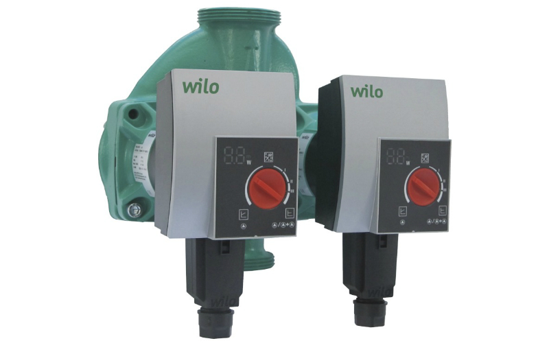
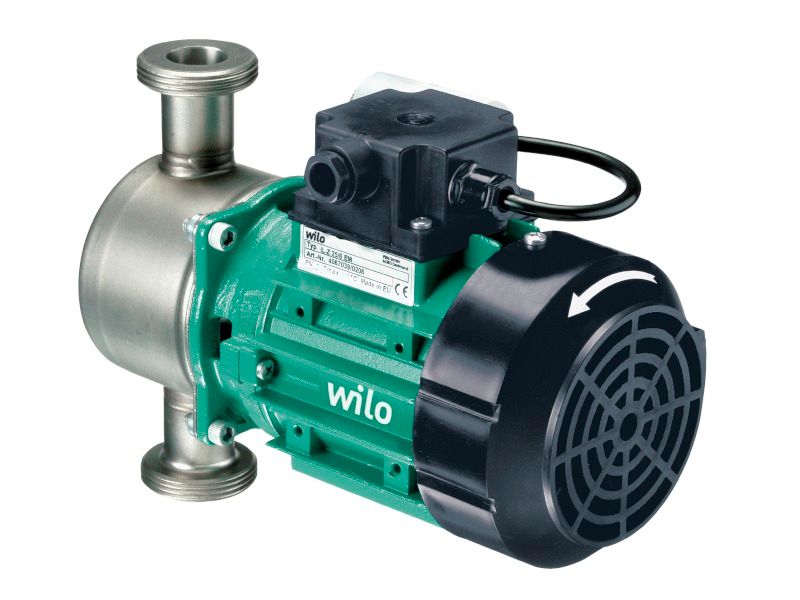
The most popular units for transporting water with wet-type rotors are products manufactured by German, Danish and Canadian companies. A special place among the range of products is the Wilo pump.
The devices have a threaded connection and are equipped with a speed control system to control the performance and power of the pump. Wilo units are used in heating and air conditioning systems, as well as in cold water circulation systems in enterprises.
Grundfos pumps
One more leader in the modern Russian and world markets of pumping equipment. Such pumps are characterized by high performance and reliability. Thanks to careful assembly from scrupulous Danes, the units work without failures and breakdowns for a long time.
Distinctive features of such mechanisms are:
- Absolute inertness to water and anticorrosion properties of the metal;
- No need for frequent preventative maintenance and repair (wet rotor does its job);
- Reliable housing tightness.
Important: Grundfos pump casings are equipped with a special heat-shielding casing, which prevents the risk of possible burns to the user.
Rotary pump – This is a volumetric pump in which liquid is displaced from displaced working chambers as a result of rotational or rotational and reciprocating movement of working bodies - displacers.
The working chamber of a rotary pump is limited to the surfaces of the constituent elements of the pump: a stator, a rotor, and a displacer (one or several).
By the nature of the movement of the working bodies (displacers), rotary pumps are rotary-rotary and rotary-translational (classification scheme according to GOST 17398-72 see in Fig. 2).
Rotary rotary pumps
In rotary rotary pumps, displacers perform only rotational motion. These include gear (gear, rotary) and screw pumps. In gear pumps, working chambers with liquid move in a plane perpendicular to the axis of rotation of the rotor, in screw pumps - along the axis of rotation of the rotor.
Rotary progressive pumps
In rotary-progressive pumps, displacers perform both rotational and reciprocal movements. These include vane (vane, figure-vane) and rotary piston pumps (radial, axial). In rotary piston displacers are usually made in the form of pistons or plungers, which are located radially or axially with respect to the axis of rotation of the rotor. All rotary-progressive pumps can be made both in the form of adjustable machines, that is, with a variable displacement, and not adjustable. All rotary rotary pumps are unregulated.
Fig. 2. Pump classification
Due to the fact that rotary pumps move the working chambers with liquid from the suction cavity to the discharge cavity, these pumps differ from piston (and plunger) pumps in the absence of suction and pressure valves. These and other design features of rotary pumps determine their common properties, which are also different from the properties of piston pumps, namely: reversibility, that is, the ability to work as hydraulic motors (hydraulic motors) when the fluid is supplied to them under pressure; higher speed (up to 3000 - 5000 rpm) and greater uniformity of feed than piston pumps; the ability to work only on clean, non-aggressive fluids with lubricating properties (the use of rotary pumps for water supply is excluded).
- 532 views