A tightening of threaded connections of the KAMAZ engine 740.10. Transport: history and modernity
1.5 Technical specifications for assembly
The parts arriving for assembly must be cleaned of dirt, varnish deposits, carbon deposits, scale, degreased, washed, dried. After cleaning, the oil channels and holes in the parts are rinsed under pressure and purged with compressed air. They must comply with the drawings and technical specifications of the manufacturer. Technological operations of engine assembly are carried out both at specialized posts and on the production line.
I propose to carry out the following work at specialized posts:
Assembly of crankshafts (Figure 1.2) and camshafts;
1- crankshaft; 2 - a counterbalance of a cranked shaft; 3 - a stub;
4 - a gear wheel leading an oil pump drive; 5 - segment key
Figure 1.2 - The crankshaft assembly.
The crankshaft is blown with compressed air before assembly. Assembly crankshaft is made in the following sequence: centrifugal oil treatment bushings are installed in the cavity of the oil channels of the necks. From above the channels are pressed with plugs. After that, gears and balances are pressed onto the shaft. An oil pump drive gear and a front remote counterweight are installed on the toe of the crankshaft, a distribution gear assembly with an oil deflector and a rear remote counterweight are installed on the shank.
Before mounting the gears and balances are heated to a temperature of 105 ° C. The gear is pressed into the shaft shoulder as far as it will go.
Before installing the crankshaft in the block, the crankshaft is balanced relative to the axis of the extreme root journals on the balancing machine. Before balancing, a load weighing 525 1 g is installed on each neck. The centers of gravity of the loads must coincide with the axles of the connecting rod necks. Permissible imbalance can be no more than 80 g. The imbalance is eliminated by removing the metal by drilling in counterweights made in one piece with the shaft.
The camshaft is assembled with the rear bearing housing and the camshaft before being installed in the engine block. Before installation, the gear is heated to a temperature of 10010 ° C and pressed onto the neck until it stops. The clearance between the gear and the bearing housing should be 0.25 - 0.30 mm;
Connecting Rod Assembly - piston group: the piston with the finger and connecting rod is assembled after heating the piston to a temperature of 80-100 ° C. The inner surface of the upper connecting rod head and pin are preliminarily greased with diesel oil. The finger is set by the force of the thumb. Pressing a finger into the piston is not allowed. Piston fingers from axial movement are fixed by retaining rings.
Piston pins must be sized before mounting on the piston. The piston ring clearance is measured in caliber with a diameter of mm.
Compression and oil scraper rings are installed using a plunger expander of oil scraper rings. It is inserted into the piston groove and the ring is put on there so that the expander joint is at an angle of 180 ° to the ring lock. After that, a compression ring coated with molybdenum and a compression ring coated with chrome are installed. Locks of adjacent rings are divorced in different directions.
The cylinder block is mounted on the wall using an overhead crane. At the stand, plugs, plugs, lower and upper O-rings of the cylinder liners are inserted into the cylinder block without twisting and undue stretching, after which the cylinder liners are installed in the nests. On the upper end of each liner, on the side facing the fan, is the cylinder number. Upon completion of the above technological operations, a hydraulic test of the cylinder block with the sleeves assembly on the stand is carried out. After hydrotesting, the bearings are placed in the bed of the main bearings. Immediately before installing the crankshaft in the block, the working surface of the main bearing shells and the main shaft journals are lubricated with pure M8G2k oil. The dimensions of the main bearing shells must correspond to the dimensions of the crankshaft necks and the seats in the cylinder block. Thrust half rings of the shaft are installed in the undercut of the last main bearing so that the sides with grooves are adjacent to the thrust ends of the shaft. The bolts of the main bearing caps are pre-tightened from the right and then from the left side of the cylinder bank with a tightening torque of 90-120 Nm, and then finally with a tightening torque of 210-235 Nm.
Before installing the camshaft, bushings are installed in the cylinder block, after which a camshaft is installed on which the journal journals are pre-lubricated with diesel oil. The camshaft is installed carefully, without damaging the working surfaces of the bushings.
The installation of pistons, pre-assembled with connecting rods and fingers in a specialized post, in the cylinder liners is done by the hand effort carefully, avoiding the cutting of the sealing rings protruding from the grooves using a special device. Before installing the connecting rod-piston group, “CIATIM” grease is applied to the chamfers of the cylinder liners. When installing the piston in the sleeve, the recesses for the valves on the piston should be offset closer to the axis of the crankshaft. The lower heads of the connecting rods are put on the connecting rod journals of the crankshaft and are closed by covers. The pairing of covers with connecting rods is checked according to the marks of the manufacturer. On the covers of the connecting rods, the cylinder serial number is knocked out. Tightening of bolts of fastening of covers of rods is made with effort of 160-130 Nanometers.
The next operation is the installation of parts of the gas distribution mechanism that transmit the force from the camshaft to the rocker arms, the guide rails of the pushers complete with pushers are installed on the pins of the cylinder block, and are bolted to the block. Bolts are tightened with a tightening torque of 70-90 Nm. The rods are wiped before installation, and the tips are lubricated with diesel oil.
Next, the distribution gears are set according to the marks. Tightening the bolts securing the axis of the driving gears of the camshaft drive to the block is carried out in 2 stages with a tightening torque of 50-60 Nm. The camshaft pinion roller bearing bolt is tightened to a tightening torque of 90-100 Nm.
Before installation, pre-assembled at a specialized post, cylinder heads are sealed with gaskets. Rubber o-rings are installed flat side to the cylinder block. Each cylinder head must be mounted freely on the pins without impact. The threads of the cylinder head bolts are lubricated with a thin layer of graphite grease. The bolts are tightened in three steps to exclude the possibility of a skew head. The tightening torque should be 190-210 Nm. Next, an oil pump and an engine sump are installed.
The front cover of the cylinder block is mounted on the block assembly with the fluid coupling of the fan drive and the alternator drive pulley. Before that on crankshaft the power take-off coupling and the crankshaft washer are put on. The hydraulic coupling drive shaft is introduced into the power take-off coupling. The cover bolts are tightened with a tightening torque of 50-60 Nm.
The intake and exhaust manifolds and water pipes of the cooling system are equipped with compressed air before installation. Tightening the bolts of their fastening is done in two steps.
Before installation, the flywheel is pre-assembled with a gear rim and an installation sleeve. Before installing the flywheel on the engine, the bearings of the gearbox input shaft are pressed into the hole in the rear end of the crankshaft, and grease No. 158 is applied. During installation, the flywheel is precisely fixed relative to the crankshaft with two pins. The bolts are tightened in two steps with a tightening torque of 150-170 Nm.
One of the main criteria determining the quality of the assembly is the compliance of the tightening torques of the threaded joints indicated in the assembly specifications and implemented in practice. Tightening torques of the main threaded connections are given in table 1.3.
Pay special attention to the selection and assembly of the cylinder-piston group - each cylinder number has its own piston version number. Indices of piston options are given in table 1.4.
Table 1.3 - Tightening torques of the main threaded connections of the engine.
|
Connection Name |
Tightening torque, N |
|
Nuts of covers of radical bearings of a cranked shaft |
|
|
Camshaft Bearing Bolts |
|
|
Cylinder block retaining bolts |
|
|
Connecting Rod Nuts |
|
|
Flywheel housing bolts |
|
|
Bolts of fastening of a hydraulic coupling of a drive of the fan |
|
|
Cylinder Head Cap Bolts |
|
|
Valve Adjustment Screw Nuts |
|
|
Oil pump mounting bolts |
|
The distance from the generatrix of the connecting rod journal in its upper position to the end of the sealing lip of the sleeve, mm |
Piston Option Index |
The distance from the axis under the piston pin to the piston bottom, mm |
|
260,12 - 260,24 |
75,67 – 75,71 |
|
|
260,24 - 260,35 |
75,78 – 75,82 |
|
|
260,35 - 260,46 |
75,89 – 75,93 |
|
|
260,46 - 260,57 |
76,00 – 76,04 |
On the piston, the index is selected on the bottom, and on the sleeve it is placed on the body, while the old markings on both the sleeve and the piston must be removed or clogged.
Of great importance is the correct marking and selection of repair dimensions of the crankshaft. The parameters of the repair dimensions are given in table 1.5. The designation of the liners of the corresponding neck, the diameter of the bed in the connecting rod is applied on the back of the liner.
Table 1.5 - Parameters of repair dimensions of the crankshaft
|
Parameter |
Repair Dimensions |
|||||
|
Nominal |
fourth |
|||||
|
The diameter of the hole for the crankshaft liner in the block |
||||||
|
Marking of a cranked shaft on radical bearings |
||||||
|
The diameter of the crankshaft main journals |
||||||
|
Marking of radical loose leaves |
||||||
Industry norms of time for production
The nomenclature and the complexity of the work performed are taken from and summarized in table 1.6
Table 1.6 & The annual complexity of the work performed
|
Name of types of work |
Distribution percentage |
The complexity of work, people / h |
Annual production program |
The annual volume of work, people / h |
|
Sleeves installation and hydraulic testing of cylinder blocks |
||||
|
Assembly piston - piston group |
||||
|
Crankshaft and camshaft assembly |
||||
|
Installation of crankshaft and camshafts |
||||
|
Installation of the piston - piston group |
||||
|
Installation of block heads |
||||
|
Continuation of Table 1.6 |
||||
|
Installing the fluid coupling of the fan drive and camshaft cover |
||||
|
Oil pump installation |
||||
|
Fuel equipment installation |
||||
|
Total per branch |
taken off; ... characteristics of the line (zone), branches MOT (TR) ... 1.3.1 Payment car fleet Payment payroll ... | |||
) separate for each cylindermade of aluminum alloy. Cylinder head has a cooling cavity in communication with the cooling cavity of the unit.
To strengthen the bottom of the head, its thickness was increased in the area of \u200b\u200bthe exhaust channel and an additional rib was made in comparison with the cylinder head 740 engine.10.
Each cylinder head is mounted on two locating pins, pressed into the cylinder block, and fastened with four alloy steel bolts. One of the locating pins simultaneously serves as a hub for oil supply to lubricate the rocker arms. The sleeve is sealed with rubber rings. In the head compared to the head 740 engine.10, enlarged engine oil drain hole from under the valve cover into the rod cavity. The windows of the inlet and outlet channels are located on opposite sides of the cylinder head. The inlet channel has a tangential profile to ensure optimal rotational movement of the air charge, which determines the parameters of the working process and environmental performance of the engine, therefore replacing the cylinder heads with a mod. 740.10 is not allowed.
Cast iron seats and ceramic-metal valve guides are pressed into the head. Valve seats have an increased interference fit compared to mod engine seats. 740.10, and are fixed with a sharp edge. The outlet seat and valve are profiled to provide less resistance to exhaust emissions.
Application of exhaust valve mod. 740.10 is not recommended.
The joint "cylinder head - liner" (gas joint) - without laying ( fig. Gas joint ) A steel sealing ring 3 is pressed into the bored groove on the lower plane of the head. Through this ring, the cylinder head is mounted on the sleeve collar. The tightness of the seal is ensured by high precision machining of the mating surfaces of the sealing ring and cylinder liner 5. The sealing ring additionally has a lead coating to compensate for microroughnesses of the sealing surfaces.
Gas joint: 1 - cylinder head; 2 - a ring sealing bypass of a cooling liquid; 3 - gas joint ring; 4 - filler gasket; 5 - cylinder liner; 6 - a sealing ring; 7 - sealing gasket; 8 - cylinder block; 9 - screen.
To reduce harmful volumes in the gas joint, a fluoroplastic gasket - filler 4 is installed. The gasket - filler is fixed on the protruding belt of the gas joint ring due to the inverse cone with an interference fit. The use of aggregate gaskets reduces specific fuel consumption and exhaust smoke. One-time placeholder.
To seal the bypass channels of the coolant, sealing rings 2 made of silicone rubber are installed in the holes in the bottom of the head.
The space between the head and the block, the engine oil drain holes and the rod passage holes are sealed with a gasket 7 of the cylinder head made of heat-resistant rubber.
When assembling the engine, the cylinder head bolts should be tightened in three steps in ascending order of numbers indicated on fig. Tightening Torque Sequence must be:
- 1 dose - up to 39-49 N.m (4-5 kgf.m);
- 2 reception - up to 98-127 N.m (10-13 kgf.m);
- 3 reception - up to 186-206 N.m (19-21 kgf.m).
Before screwing, grease the threads of the bolts with a layer of graphite grease.
After tightening the bolts, it is necessary to adjust the gaps between the valves and the rocker arms. The valve mechanism is closed by an aluminum cover 15 (see. Fig. The gas distribution mechanism). For noise insulation and sealing the joint of the cap - cylinder head, a vibration isolation washer 14 and a rubber gasket 19 were used.
Tightening Torque Sequence
Tighten the cylinder head cover bolts with a torque of 12.7-17.6 N.m (1.3-1.8 kgf.m).
Each head of the Kamaz-740 block is mounted on two locating pins, pressed into the cylinder block, and is fastened with four alloy steel bolts.
One of the locating pins simultaneously serves as a hub for oil supply to lubricate the rocker arms. The sleeve is sealed with rubber rings.
Compared to the engine head 740.10, the KamAZ-740 cylinder head has a larger hole for draining engine oil from under the valve cover into the rod cavity. The windows of the inlet and outlet channels are located on opposite sides of the cylinder head.
The inlet channel has a tangential profile to ensure optimal rotational movement of the air charge, which determines the parameters of the working process and environmental performance of the engine, so replacement with the cylinder heads of the 740.10 engine is not allowed.
Cast iron seats and ceramic-metal valve guides are pressed into the cylinder head of the Kamaz-740. The valve seats have an increased interference fit compared to the 740.10 engine seats and are fixed with a sharp edge.
The outlet seat and valve are profiled to provide less resistance to exhaust emissions. The use of an exhaust valve 740.10 is not recommended.
The joint "cylinder head - liner" Kamaz-740 (gas joint) is unlined. A steel seal ring is pressed into the bored groove on the lower plane of the head.
Through this ring, the Kamaz-740 cylinder head is mounted on the sleeve collar. The tightness of the seal is ensured by high precision machining of the mating surfaces of the sealing ring and cylinder liner.
The sealing ring additionally has a lead coating to compensate for microroughnesses of the sealing surfaces.
1 - cylinder head, 2 - cylinder head gasket, 3 - cylinder head bolt, 4 - cylinder head cover, 5 - cylinder head bolt, 6 nipple gasket, 7 - gas joint seal, 8 - intake valve, 9 - seat valve, 10 - valve guide bush, 11 - washer of valve springs, 12 - external and internal valve springs, 13 - plate of valve springs, 14 - valve plate, 15 - valve cracker, 16-seal sleeve, 17 - inlet valve
The valve mechanism and nozzle are located in the cylinder heads. The valve mechanism of the head is closed by an aluminum cover sealed by a gasket. Cast iron seats and ceramic-metal valve guides are bored after they are pressed into the head.
Each head is attached to the cylinder block with four bolts. To avoid a violation of the tightness of the gas joint, the bolts are tightened in a cross pattern in three steps.
The inlet and outlet channels are located on opposite sides of the head. When looking at the engine from the side, the intake valves of the heads are on the right, and the exhaust valves are on the left.
The inlet channel has a tangential profile, providing swirling air movement in the cylinder, improving mixture formation and accelerating the combustion process of the injected fuel. The nozzle socket is located on the side of the exhaust valve at an angle to the axis of the cylinder.
Dismantling the engine block head
To remove the cylinder head have to quite often. At least every 40-50 thousand kilometers. So the KamAZ engine is structurally designed. The cause is leaking coolant or oil. Dismantling the cylinder head will also be required to repair the piston group or the gas distribution mechanism.
Let's take a stepwise and detailed look at the process of dismantling the head of the KamAZ 740 engine block.
1. Drain at least half the volume of coolant from the cooling system.
2. To dismantle the cylinder heads of some cylinders, it will be necessary to dismantle the coolant expansion tank and compressor.
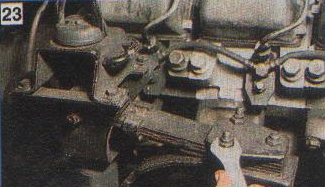
3. Remove the intake and exhaust manifolds, as well as unscrew all interfering fuel supply pipes.
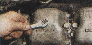
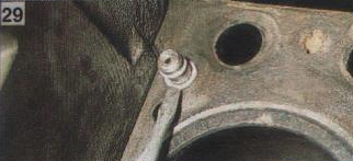
4. We turn off a bolt of fastening of a cover of a head of the block with a key on 13.
5. Remove the cover and gasket.
 6. If you need to remove only one head, you will have to remove the cover from the adjacent block head so that its protrusion does not interfere with dismantling.
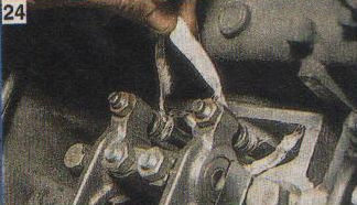
 7. To dismantle the cylinder head of the fourth and eighth cylinders, you will need to unscrew the nuts securing the cab springs with a 17 key and take them to the side along with the shock absorbers.
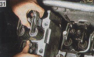
 8. It is desirable to fix the gas distribution mechanism rods, for example, by interconnecting them in order to avoid falling into the pallet when removing the cylinder head.
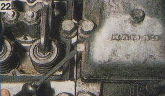
9. Unscrew the four bolts securing the head to the block with a socket wrench or socket wrench at 19.
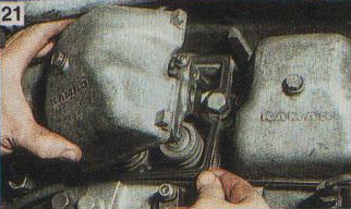
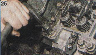 10. Remove the head of the block by prying with a mounting spatula and at the same time swinging it by inserting the bolts of the fastening of the winch into the hole.
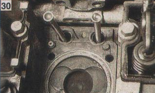
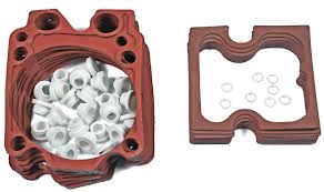
11. The head should be cleaned of dirt and carbon deposits. After that, replace the three o-rings ("barrels") of the water holes.
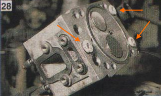 O-rings are included in the repair kit for mechanical rubber goods of the head of the KamAZ 740 engine block. In the vocabulary vocabulary of auto-makers there is their name - a keg.
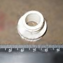
12. Put a new sealing ring on the sleeve of the oil channel.
 13. Install a new cylinder head gasket on the engine block and put the rods in place.
 14. Replace the block head. The cylinder head bolts should be tightened crosswise in three steps.
The final tightening torque of the bolts of the KamAZ 740 engine block head is 16-18 kgf * m.
Repair kit gaskets RTI engine block heads
The kit consists of:
1.740.1003 040 O-ring, oil channel - 16 pcs.
2. 740.1003 214-04 O-ring (cylinder head) "barrel", is installed in the holes of the coolant channels - 24 pcs.
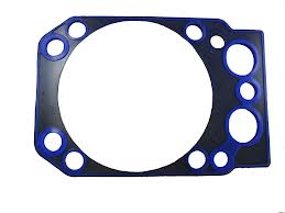
3. 740.1003 213-26 Gasket gasket cylinder head - 8 pcs.
4. 740.1003270 Gasket, sealing of the cylinder head cover - 8 pcs.
Cylinder head gaskets can be old and new designs.
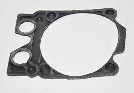
Old cylinder head gasket
Repair engine head
Given the interchangeability of the heads of the KamAZ 740 engine block, repair is preferable to replacing the cylinder head with a new one.
If necessary, repairs are often carried out:
- Replacing valve seats.
- Seat processing - lapping valves.
- Saddle boring .
- Plane recovery
TO category:
Car Maintenance
Technical conditions for the assembly of the KamAZ-740 engine
Installing cylinder liners and guide pushers.
The upper O-rings must be installed on the cylinder liners without twisting and excessive stretching.
Before installing the sleeves in the block, the TsIATIM type grease must be applied to the entry chamfers of the block and sleeves. The sleeves should be inserted into the unit carefully by hand, not allowing the o-rings protruding from the grooves to be cut off.
On the upper non-working end of each sleeve on the side facing the fan, it is necessary to put the cylinder number.
The guides of the pushers should come to the assembly complete with pushers. All guides and pushers installed on one engine must have the size according to the working drawing or repair. The guides should be installed on the pins of the cylinder block and bolted. The tightening torque of the bolts should be 7.5-9.5 kgf-m.
Assembly and installation of a camshaft. The camshaft must be assembled with the bearing housing and gear. Before assembling with the bearing housing, the back support journal of the shaft and the housing sleeve must be wiped with a napkin and greased with clean engine oil.
Press the gear, preheated to a temperature of (100 ± 10) ° С, onto the shaft journal as far as it will go. The clearance between the gear and the bearing housing should be 0.25-0.30 mm.
When installing the camshaft in the cylinder block, lubricate the bushings of the bearings and the journal journals with clean engine oil. The camshaft should be installed carefully; damage to the working surfaces of the bushings is not allowed.
Assembly and installation of the crankshaft. Before assembling, it is necessary to carefully blow the crankshaft with compressed air. In the shaft cavity, press in and expand the plugs, and insert a screwdriver into the oil channel of the front end, As shown in Fig. 2. The depth of the end face of the screwdriver from the end of the shaft should be at least 56.5 mm. The tightening torque of the screwdriver should be 5-6 kgf-m. Check the tightness of the plugs by pressure testing the cavities with diesel fuel under a pressure of 2 kgf / cm2. Leakage of fuel is allowed no more than 20 g / min for one plug. After checking, to remove fuel, it is necessary to blow out the channels and cavities of the shaft. It is allowed to check the tightness of plugs with oil at a temperature of 40-50 ° C under a pressure of 10 kgf / cm2; oil leakage for one plug should not be more than 20 g / min. Reinstallation of used plugs is not allowed.
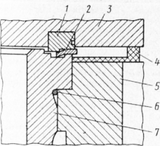
Fig. 1. Joints of the cylinder head and liner, head and cylinder block of the KamAZ engine: 1 - support ring; 2 - cylinder head gasket; 3-cylinder head; 4 - rubber head gasket; 5 - cylinder block; 6 - sealing ring of the sleeve; 7- sleeve
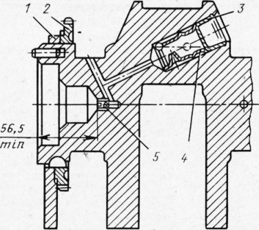
Fig. 2. Installing plugs for the channels of the crankshaft: 1 - front counterweight; 2-gear oil pump drive; 3-stub; 4 - sleeve; 5 - cap screwdriver
The mounting pins must be pressed into the crankshaft so that the pin on the front end of the shaft protrudes by 7 mm and the rear by 10 mm.
Heat the gears and balances before pressing to a temperature of 105 ° C. Pressing to the stop. Counterweights are made with an imbalance of 13,500 g-cm relative to the axis of the hole with the direction of action along the axis of symmetry of the counterweight. Deviation from a given imbalance should not exceed 15 gf-cm in any direction.
The dimensions of the main bearing shells must correspond to the dimensions of the crankshaft necks and the seats in the cylinder block. Before installing the crankshaft in the block, the working surface of the main bearing shells and the main journals must be lubricated with clean engine oil. Install the axial half rings of the crankshaft in the recesses of the rear main bearing so that the sides with the grooves are adjacent to the axial ends of the shaft. Tighten the main bearing cap bolts in accordance with the instructions given in the technical specifications for repair of the afterburner.
Installation of timing gears. Gears should be installed on labels, as shown in fig. 78. Tighten the bolts of the axle of the driving gear of the camshaft drive to the block in two stages (preliminary and final) with a torque of 5.0-6.2 kgf-m. Tighten the camshaft pinion roller bearing mounting bolt to 9-10 kgf-m.
The circumferential clearance in the engagement of the timing gears when the engine is in working condition should be 0.1-0.3 mm. Measure the circumferential clearance with a probe at three points (at least).
Assembly and installation of flywheel housing. The crankcase is assembled with a front bearing housing and a sleeve for the rear end of the crankshaft. Before installing the crankcase, the cylinder block along the perimeter of the flywheel crankcase gasket may be lubricated with a thin layer of UT-2 constalin or with lubricants 1-13, TsIATIM -201. Tighten the flywheel housing bolts to a torque of 9-11 kgf-m.
The radial runout of the landing diameter and the axial end of the flywheel housing under the clutch housing relative to the axis of the crankshaft should not exceed 0.4 mm.
Assembly and installation of the piston with a finger and a connecting rod. A piston with a finger and a connecting rod is assembled after heating the piston to 80 -) (10 ° C. The hole in the connecting rod under the finger and the finger itself must be liberally lubricated with engine oil. The finger is installed by hand (pressing is not allowed).
Recesses for valves on the piston and grooves for the mustache of the liners on the connecting rod must be positioned in one direction. The piston pin retaining rings must securely lock it in the piston against axial movement.
On the connecting rod cap, it is necessary to knock out the cylinder serial number, having previously checked the pairing of the cap with the connecting rod.
Install compression and oil scraper rings on the piston using a special tool. Install the oil scraper ring in series: first insert the spring expander into the groove, then put on the ring so that the expander joint is at an angle of 180 ° to the ring lock.
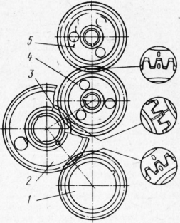
Fig. 3. Installation of distribution gears: 1 - drive gear; 2,3 - intermediate gears; 4 - a camshaft gear; 5 - gear drive fuel pump
Then install the compression ring coated with Mplia ^ and, and the last - the compression ring coated with chrome. Locks adjacent rings to part in opposite directions.
Install kits with pistons and rings assembly on the engine in accordance with the cylinder numbers stamped on the connecting rod cover. The cylinder numbering is shown in fig. 4. When installing the piston in the sleeve, the recesses under the valves on the piston should be offset closer to the axis of the crankshaft.
The total gap between the ends of the lower heads of the connecting rods and the cheeks of the crankshaft (axial play) should be at least 0.15 mm. The protrusion of the piston bottom above the shoulder of the liner should be in the range of 0.5-0.7 mm.
The bolts securing the connecting rod caps must be tightened to an extension of 0.25-0.27 mm.
Assembly and installation of a flywheel. The flywheel must be assembled with a gear rim and an installation sleeve. When installing on the flywheel, the toothed rim must be heated to a temperature of 230 ° C. The mounting sleeve must be assembled with the input shaft collar and pressed into the flywheel until it stops.
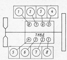
Fig. 4. The scheme of the numbering of the cylinders of the KamAZ engine and the location of the sections of the injection pump
Fig. 5. Flywheel assembly of the KamAZ engine: 1 - gear ring; 2 - flywheel; 3 - a persistent ring; 4 - installation sleeve; 5 - an epiploon of a primary shaft of a transmission
Before installing the flywheel on the engine, press the input shaft bearing of the gearbox into the hole in the rear end of the crankshaft and put 15 g of grease No. 153. Tighten the flywheel mounting bolts sequentially in two stages (preliminary and final) with a torque of 15-17 kgf-m. The runout of the working surface of the flywheel and the near-roll surface under the clutch cover, measured at maximum diameters relative to the axis of the crankshaft, should not exceed 0.25 mm.
Assembly and installation of cylinder heads. The cylinder head must be thoroughly blown with compressed air before assembly. The support ring of the gas joint after installation in the head must be crimped with a force of 4500 kgf. The protrusion of the plane of the ring from the head after crimping should be 0.122-0.230 mm. The measurement difference for one head should not exceed 0.08 mm. The protrusion of the gas joint ring should not have any burrs or nicks.
Valve seating must be airtight. Leak test with dry air at a pressure of 1.5 kg / cm2. Permissible air leakage should not exceed 3.6 cm / min. Valves must be securely fixed with crackers.
Before installing the cylinder head, the interface plane of the block and the head, as well as the gasket, must be wiped and blown with compressed air. The cylinder head rubber o-rings should be installed with the flat side facing the cylinder block. The cylinder head should fit freely onto the dowel pins without impact. The threads of the cylinder head bolts must be lubricated with a thin layer of graphite grease. The bolts are tightened in the sequence shown in fig. 81. The bolts must be tightened in at least three steps: 1st — 4 kgf-m; 2nd - 124-15; 3rd - 19-Н21 kgf-m (limit values).
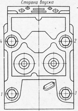
Fig. 6. The order of an inhaling of bolts of fastening of a head of the cylinder of the KamAZ engine
TO Category: - Car Maintenance
Crank mechanism of KamAZ engines 740.11-240, 740.13-260, 740.14-300
Crankshaft of KamAZ 740.11-240, 740.13-260, 740.14-300 engines
Crankshaft (see fig.) is made of stainless steel and has five main and four connecting rod necks, hardened by HDTV, which are connected by cheeks and mate with them by transition fillets. For uniform alternation of working strokes, the crankshaft connecting rod journals are arranged at an angle of 90 °.
Crankshaft : 1 - front crankshaft counterweight; 2 - rear crankshaft counterweight; 3 - gear drive oil pump; 4 - a gear drive of a gas distribution mechanism; 5.6 - key; 7 - pin; 8 - nozzle; 9 - lightening holes; 10 - holes for supplying oil in the main necks; 11 - holes for supplying oil to the connecting rod journals .
Two connecting rods are attached to each crank pin. connecting rod: one for the right and one for the left row of cylinders ( Connecting rod ).
The oil supply to the connecting rod journals is made from the holes in the main journals 10 by straight holes 11.
To balance the forces of inertia and reduce vibrations, the crankshaft has six counterweights, stamped at the same time with the cheeks of the crankshaft. In addition to the main counterweights, there are two additional removable counterweights 1 and 2, pressed onto the shaft, while their angular location relative to the crankshaft is determined by keys 5 and 6 ( fig. Crankshaft ).
Ball bearing 5 is pressed into the bore of the crankshaft shank ).
A nozzle 8 is screwed into the cavity of the front toe of the crankshaft, through the gauge hole of which the spline power take-off roller is lubricated to the hydraulic clutch drive.
From axial displacements, the crankshaft is fixed by two upper half rings and two lower half rings 2 ( Fig. Installation of persistent half rings and crankshaft bearing shells ) installed in the grooves of the rear main support of the cylinder block, so that the side with grooves is adjacent to the thrust ends of the shaft. On the front and rear socks of the crankshaft ( fig. Crankshaft ) The gear 3 of the pump oil drive and the drive gear 4 of the camshaft drive are installed. The rear end of the crankshaft has eight threaded holes for the flywheel bolts, the front toe of the crankshaft has eight holes for attaching the vibration damper.
The seal of the crankshaft is carried out with a rubber sleeve 8 ( Fig. Installing the flywheel and crankshaft seal ), with an additional sealing element - anther 9. The cuff is placed in the flywheel housing 4. The cuff is made of fluororubber according to the technology of forming the working sealing edge directly in the mold.
The diameters of the necks of the crankshaft: radical 95 ± 0,011 mm. connecting rod 80 ± 0.0095 mm.
Recovery kamAZ engine Eight repair liner sizes are provided. The designation of the crankshaft bearing shells, the diameter of the crankshaft main neck, the bore diameter in the cylinder block for these shells are shown in Appendix 1.
The designation of the liners of the lower connecting rod head, the diameter of the connecting rod neck of the crankshaft, the diameter of the holes in the lower connecting rod head for these liners are shown in Appendix 2.
The bushings 7405.1005170 P0, 7405.1005171 P0, 7405.1005058 P0 are used when restoring the engine without grinding the crankshaft. If necessary, the crankshaft journals are polished. The tolerances on the diameters of the necks of the crankshaft, the holes in the cylinder block and the holes in the lower head of the connecting rod during engine repair should be the same as the nominal sizes of new engines.
Main and connecting rod bearings of KamAZ 740.11-240, 740.13-260, 740.14-300 engines
Indigenous and connecting rod bearingsmade of steel tape coated with a layer of lead bronze 0.3 mm thick, a layer of lead-tin alloy 0.022 mm thick and a tin layer 0.003 mm thick. Top 3 ( Fig. Installation of persistent half rings and crankshaft bearing shells ) and lower 4 indigenous liners bearingsnot interchangeable. In the upper liner there is a hole for oil supply and a groove for its distribution. Both liners 4 of the lower connecting rod head are interchangeable.
From turning and lateral displacement, the liners are fixed by the protrusions (mustache) included in the grooves provided in the unit’s beds, covers bearings and in the connecting rod beds. The liners have structural differences aimed at increasing their performance during forcing engine turbocharging, while changing the marking of the liners to 7405.1004058 (connecting rod), 7405.1005170 and 7405.1005171 (indigenous).
Therefore, when carrying out repairs, it is not recommended to replace the liners with serial ones with the marking 740.100 .., since this will significantly reduce the resource engine.
Installation of persistent half rings and liners of bearings of the crankshaft: 1 - half ring of the thrust bearings of the crankshaft; 2 - lower ring of the thrust bearing of the crankshaft; 3 - top bearing shell of the crankshaft; 4 - lower crankshaft bearing shell; 5 - cylinder block; 6 - the back cover of the crankshaft bearing; 7 - a cranked shaft.
Covers of main bearings of engines KAMAZ 740.11-240, 740.13-260, 740.14-300
Covers main bearings (Fig. Installing crankshaft bearing caps ) are made of ductile iron of the VCh50 brand. The lids are fastened with the help of vertical and horizontal coupling bolts 3, 4, 5, which are tightened according to a certain pattern with a regulated torque.
Installation of crankshaft bearing caps: 1. Crankshaft bearing cap; 2. Crankshaft; 3. Bolt of fastening; 4. Bolt of coupling fastening of a cover of the bearing left; 5. A bolt of coupling fastening of a cover of the bearing right; 6. Washer 7. Block.
The connecting rod of KamAZ engines 740.11-240, 740.13-260, 740.14-300
Connecting rod (see pic.)steel, forged, rod 1 has an I-section. The upper head of the connecting rod is one-piece, the lower one is made with a straight and flat connector. Connecting rodfinally processed complete with cover 2, so the connecting rod covers are not interchangeable.
A steel-bronze bushing 3 is pressed into the upper head of the connecting rod, and replaceable liners 4 are installed in the lower one. The connecting rod bolts are tightened according to the scheme defined in Appendix 8. The mating marks are applied on the cover and rod of the connecting rod - three-digit serial numbers. In addition, the cylinder serial number is knocked out on the connecting rod cover.
Connecting rod
Flywheel of engines KAMAZ 740.11-240, 740.13-260, 740.14-300
Flywheel 1 (see pic . Flywheel ) secured with eight bolts 7 ( ), made of alloy steel with a twelve-headed head, at the rear end of the crankshaft and precisely fixed with two pins 10 and an installation sleeve 3 ( see pic . Flywheel ).
Flywheel
Installing the flywheel and the seal of the crankshaft: 1 - flywheel; 2 - cylinder block; 3 - a cranked shaft; 4 - flywheel housing; 5 - a bearing of a primary shaft of a transmission; 6 - washer; 7 - flywheel mounting bolt; 8 - a cuff of consolidation of a cranked shaft; 9 - boot cuff; 10 - a pin adjusting a flywheel.
In order to avoid surface damage flywheel a washer 6 is installed under the bolt heads ( Fig. Installing the flywheel and crankshaft seal cuffs ) The magnitude of the tightening torques of the flywheel mounting bolts is shown in Appendix 8. A gear ring 2 is pressed onto the machined cylindrical surface of the flywheel, with which the starter gear engages when starting the engine ( see pic . Flywheel ).
When performing adjustment work to set the lead angle of fuel injection and the values \u200b\u200bof thermal clearances in the valves flywheel fixed with a latch ( Fig. Handwheel Lock Knob Positions ).
Positions of the handle of the flywheel retainer: a) - during operation; b) - during adjustment, in engagement with the flywheel.
Moreover, the design has the following main differences from the serial:
- the angle of the groove under the retainer on the outer surface of the flywheel has been changed;
- the diameter of the bore is increased to accommodate the washer under the flywheel bolts.
Considered kamAZ enginescan be equipped with various types of clutches. On the fig. Flywheel the handwheel for diaphragm clutch is shown.
Torsional vibration damper of KamAZ 740.11-240, 740.13-260, 740.14-300 engines
Torsion damper secured with eight bolts 2 ( fig. Installing a torsional vibration damper ) on the front toe crankshaft . In order to avoid damage to the surface of the damper body, a washer 5 is installed under the bolts. Extinguisherconsists of a housing (see figure) in which a flywheel is installed with a clearance. Outside, the damper body is covered with a lid. Tightness is ensured by rolling (welding) at the junction of the damper body and cover. Between the damper body and the flywheel there is a highly viscous silicone fluid dosed before filling the lid.
The damper is centered by a washer welded to the body ( fig. Torsional vibration damper ) Damping torsional vibrations of the crankshaft occurs by braking the damper body, mounted on the toe of the crankshaft, relative to the flywheel in an environment of silicone fluid. In this case, the braking energy is released in the form of heat. During repair work, it is strictly forbidden to deform the case and the damper cover. The damper with a deformed body or cover is not suitable for further use.
Installation of a torsional vibration damper of the crankshaft: 1 - damper; 2 - damper bolt; 3 - coupling for power take-off; 4 - a coupling bolt; 5 - washer; 6 - a cranked shaft; 7 - cylinder block
Torsional vibration damper
The piston of engines KAMAZ 740.11-240, 740.13-260, 740.14-300
Piston 1 ( ) cast from aluminum alloy with an insert of wear-resistant cast iron under the upper compression ring.
In the head piston made toroidal combustion chamber with a displacer in the Central part, it is offset relative to the axis piston5 mm away from the grooves under the valves.
The lateral surface is a complex oval-barrel-shaped with an understatement in the area of \u200b\u200bthe holes under the piston pin. The skirt is coated with graphite.
A groove is made in its lower part, which eliminates contact between the piston and the cooling nozzle when it is in the correct position.
Piston It is completed with three rings, two compression and one oil scraper. Its distinctive feature is the reduced distance from the bottom to the lower end of the upper groove, which is 17 mm. On the kamAZ engines In order to ensure fuel economy and environmental performance, selective selection of pistons for each cylinder according to the distance from the axis of the piston pin to the bottom is applied. According to the specified parameter, the pistons are divided into four groups 10, 20, 30 and 40. Each subsequent group differs from the previous one by 0.11 mm.
IN spare parts pistons of the greatest height are supplied, therefore, in order to avoid possible contact between them and the cylinder heads in case of replacement, it is necessary to control the piston clearance. If the gap between the piston and the cylinder head after tightening the bolts of its fastening is less than 0.87 mm, it is necessary to cut the piston bottom by an amount that is missing to this value. Pistons 740 engines.11, 740.13 and 740.14 differ from each other in the form of grooves for the upper compression and oil scraper rings. (see sections compression and oil scraper rings). Installation of pistons from engines KAMAZ 740.10 and 7403.10 are not allowed. Installation of pistons with piston rings is allowed 740 engines.13 and 740.14 on the engine 740.11. I
Connecting rod piston
Piston with connecting rod ( fig. Piston with rings assembly with connecting rod ) are connected by a finger 3 of a floating type, its axial movement is limited by retaining rings 6. The finger is made of chromium-nickel steel, the hole diameter is 22 mm. The use of fingers with a 25 mm hole is unacceptable, as this disrupts the balancing of the engine.
Compression rings of KamAZ 740.11-240, 740.13-260, 740.14-300 engines
Compression rings (fig. Piston with rings assembly with connecting rod ) are made of high strength, and oil scraper of gray cast iron. On the 740 engine.11 cross-sectional shape compression rings one-way trapezoid, during installation, the inclined end with the mark "top" should be located on the piston bottom side. On the 740 engines.13 and 740.14 the upper compression ring has the cross-sectional shape of a double-sided trapezoid with a sample at the upper end, which should be located on the piston bottom side.
Piston with connecting rod and rings assembly: 1 - piston; 2 - oil scraper ring; 3 - a piston finger; 4, 5 - compression rings; 6 - a lock ring.
The working surface of the upper compression ring 4 is coated with molybdenum and has a barrel-shaped shape. Chrome is applied to the working surface of the second compression 5 and oil scraper rings 2. Its shape on the second ring is a cone with a bias towards the bottom, according to this characteristic feature the ring is called "minute". Minute rings are used to reduce oil consumption for waste, their installation in the upper groove is not permissible.
Oil scraper ring of engines KAMAZ 740.11-240, 740.13-260, 740.14-300
Oil scraper ring box-type with a spring expander having a variable pitch of turns and a polished outer surface. The middle part of the expander with a smaller pitch of turns when installed on the piston should be located in the ring lock. On the engine models 740 .11 ring height - 5 mm and on 740 engines.13 and 740.14 ring height 4 mm.
Installation piston rings from other models kAMAZ engines may lead to increased oil consumption for waste.
To exclude the possibility of using non-interchangeable parts of the cylinder-piston group during repair work, it is recommended to use repair kits:
- 7405.1000128-42 - for the engine 740.11-240;
- 740.13.1000128 and 740.30-1000128 - for engines 740.13-260 and 740.14-300.
The repair kit includes:
- piston;
- piston rings;
- piston pin;
- piston pin retaining rings;
- cylinder liner;
- cylinder liners.
Injectors for cooling engines KAMAZ 740.11-240, 740.13-260, 740.14-300
Cooling nozzles (fig. Installing the liner and piston cooling nozzle ) are installed in the crankcase of the cylinder block and provide oil from the main oil line when it reaches a pressure of 0.8 - 1.2 kg / cm2 (the valve located in each of the nozzles is adjusted to this pressure) into the internal cavity pistons.
During assembly kamAZ engine it is necessary to control the correct position of the tube nozzles relative to the cylinder liner and piston. Contact with the piston is not permitted.
![]()
Source of information Website: http: //www.avtokama.ru/files/teh/dvigatel1.html