Types of impellers of centrifugal pumps. Centrifugal pumps: device and classification. How centrifugal pumps are classified
The invention relates to the field of centrifugal pumps. The impeller of a centrifugal pump contains at least two blades with different entry angles β l1. All impeller blades are located with a constant external pitch α and have the same exit angle β l2. In the particular case of each blade there corresponds a blade with the same angle of entry β l1, located symmetrically relative to the center of the impeller. The impeller may include three pairs of blades with different entry angles β l1. An increase in the efficiency of the pump is achieved in the range of flow values \u200b\u200bother than the calculated value. 4 s.p. f-ly, 3 ill.
Rotary pump, eccentric piston. Radial piston pumps and wheel plates A rotation of the piston bearing housing connects each piston to a corresponding suction port during the stroke of the piston and suction port in the exhaust stroke. These designs can be adapted for variable power, this is done to change the eccentricity between the housing that carries the plunger and the ring that drives the plungers, the angle between the propeller shaft and the housing carried by the plunger varies.
The invention relates to the field of centrifugal pumps, in particular, to the design of their impellers, and can be used to improve the efficiency of pumps in heating and water supply systems.
The impeller system of the impellers of the pumps is profiled for the calculated value of the pump flow based on the conditions for reducing hydraulic losses. Minimization of hydraulic losses allows you to ensure maximum efficiency of the pump in the optimal mode of operation, corresponding to the calculated value of the flow.
Actual bombs are complicated. Radial piston pump. In a pump with a flexible element, the sealing and pumping actions depend on the elasticity of the flexible elements, which can be a tube or vanes. In single-screw pumps, fluid is pumped axially between the internal threads of the stator and screw.
C) the absence of external defects - visually
The frontal type is one of the first designs used for rotary pumps and fans. They are suitable for medium and large tanks and low pressure. As with a swing piston type pump, there is a linear contact between the impeller and the housing, and leaks are excessive at high pressures. The shoulder blades are not self-acting; therefore, these pumps must be built using external pilot gears that can transmit half the power used. from the drive shaft to the driven shaft.
The main laws for profiling the impeller system of the impeller of a centrifugal pump are described in the publication: M.D. EISENSTEIN Centrifugal pumps for the oil industry. - M .: State Scientific and Technical Publishing House of Petroleum and Mining and Fuel Literature, 1957. However, an impeller designed in accordance with the indicated source will ensure minimal hydraulic losses, i.e. high pump efficiency, only in a narrow area close to the calculated pump flow values.
Gear pumps have the type of two trees and very diverse designs. They are used for almost all capacities and pressure. In many types, the rotary gears are automatic, and a pilot mechanism is not required. In the simplest form, gears are used. A large number of teeth in contact with the body minimizes peripheral leaks. The usefulness of gears is limited because they trap fluid on the discharge side at the point where the gears are connected, resulting in low noise and low mechanical efficiency, especially at high speeds.
The method of constructing a centrifugal pump impeller system was developed in the work of: A.N. MACHINES. Profiling the flow of the impellers of centrifugal pumps. - M .: Moscow Order of Lenin Power Engineering Institute, 1976. This publication details the methodology for calculating all parameters of a blade system, while a pump equipped with such an impeller also shows high efficiency only when operating in the optimal mode or near it.
Unloading cavities may be provided in the side plates to reduce the effect of liquid trapping. When simple helical gears are used at high pressures, significant traction results in the tips of the gears on the side plates of the pump. The spiral or bichelic structure of the mechanism substantially eliminates the grip effect, but leaks occur between the teeth at the attachment point if they are not cut without any gap in the root.
The difference in diameter. In pumps of this type, an impeller mounted eccentrically to the housing drives an internal gear that rotates in the housing or in bearings mounted on end plates. The flow is almost continuous and without investment. It can be used with high rotation speeds. In these pumps, leaks occur around the periphery of the crown, at the tips of the gear teeth when they begin to engage, and along the contact line when they are fully engaged. This type is especially suitable for high pressures and high speeds, for example, for oils with lubricity and significant viscosity.
Thus, impellers known from the prior art do not allow efficient use of the pump at flow rates significantly different from the calculated ones.
However, in real conditions, in particular in heat supply and water supply systems, a significant part of the time the pump is operated in a mode other than optimal, for example, with a supply value less than the calculated one. Under such conditions, the efficiency of the pump is significantly reduced. It should be noted that the manufacturer sets the calculated flow rate closer to its maximum value, since the pump must ensure stable operation in the entire claimed flow range. Consequently, the optimal operating mode of the pump does not always correspond to the operating mode, and the time-weighted average efficiency of the pump can be significantly lower than the calculated one.
Internal gear pump with one tooth difference. The difference of two teeth. In this design, stirrups or a stand are used in one of the side plates to fill the open space between the outer and inner gears. This design reduces leakage, but requires the use of an internal aircraft, which limits the use of pumps for tanks and low and medium pressures.
Internal gear pump with two teeth difference. Circular piston pumps. The fluid is pumped between the spaces of the piston surfaces; there is no real contact between the piston surfaces. Circular piston pump. In screw pumps, a single, long, small diameter, special form of screw drive drives one or more bolts contained in it, so that the pumped liquid is displaced in the axial direction. Multiple contact surfaces, rather than linear contacts between bolts and housing, minimize leakage.
The objective of the invention is to increase the efficiency of the pump in the range of pump flow values \u200b\u200bthat differ from the calculated flow value.
To solve this problem, an impeller of a centrifugal pump is proposed, which contains at least two blades having different entry angles. All the blades can have the same exit angle. All blades can be positioned with a constant outer pitch. Each blade can correspond to a blade with the same angle of entry, located symmetrically relative to the center of the impeller, while these blades form a pair. The impeller may include three pairs of blades with different entry angles.
This design allows you to work at a very high speed. Other parts, such as wear rings and wood liners, are usually added to improve performance and make the pumps more economical, as evidenced by the services in which they are used. The names recommended by the Hydraulic Institute for parts are listed in the table.
Horizontal pump, single stage, double suction, spiral. In a centrifugal pump, the liquid is forcedly supplied by atmospheric pressure or another to a group of rotating blades, which becomes an impeller, which discharges the liquid at a higher pressure and with a higher speed at its periphery. Then, most of the velocity energy is converted into pressure energy using a spiral or a group of stationary diffusion vanes surrounding the periphery of the impeller. Spiral pump pumps are called scroll pumps; those with diffuser blades are called diffuser pumps; They are sometimes called turbine pumps, but this term is applied more selectively to diffusion pumps, centrifuges. for a deep well. vertical, now called vertical turbopumps.
When using the invention, the following technical results are achieved:
Increasing pump efficiency in the range of pump flow values \u200b\u200bthat differ from the calculated pump flow value;
Increase in time-weighted average pump efficiency.
The description of the invention is illustrated by reference to the figures:
figure 1 - the original impeller;
Centrifugal pumps fall into other categories, of which several relate to the impeller. First, the impellers are classified according to the main direction of flow relative to the axis of rotation. If the pump is of a type in which a load or elevator develops with one impeller. the pump is called a single stage; when two or more sequential accelerators are used, the pump is called a multi-stage pump. The mechanical design of the enclosure adds another classification, divided axially or radially divided.
figure 2 - upgraded impeller;
figure 3 - dependence of the efficiency of the pump on the feed for the original and upgraded wheels.
The blades of the impeller shown in figure 1, have a working surface, represented in the drawing by the line L, which is hereinafter referred to as the outer line of the blade. The input edges of the blades 1 lie on the inlet circumference having a diameter D1. The output edges of the blades 2 lie on the circumference of the outlet with a diameter D2, which usually coincides with the outer diameter of the impeller. The angle between the outlet edges of the blades α, hereinafter - the outer step, is the same for all blades.
The axis of rotation determines whether the pump is horizontal, vertical or. sometimes prone. Similarly, they are called horizontal or vertical pumps. Some pumps operate with fluid that is sent to them and discharged through pipes. Other pumps. usually vertical, immersed in the suction feed. Therefore, vertical pumps are sometimes called dry or wet. If the wet wells are an axial flow, a mixed flow, or a vertical turbine, the fluid is discharged through the bottom pipe or column to the discharge point above or below the floor of its temptation.
Tangent to the outer line of the blade at the point of intersection with the circle of the entrance and tangent to the circumference of the entrance at the specified point form the angle of entry β 1l. The tangent line to the outer line of the blade at the point of its intersection with the exit circle and the tangent line to the exit circle at the indicated point form an exit angle β 2l.
The values \u200b\u200bof the parameters D1, D2, β 1l and β 2l are determined for the calculated pump flow, subject to maximization of the pump efficiency, as well as subject to design restrictions, and are the same for all blades. Because, as shown in the above work, A.N. The machine, the coupling of the entry and exit angles can be carried out by a smooth curve of arbitrary shape, then we can assume that these parameters determine the shape and location of the impeller blades. All blades of such an impeller, hereinafter referred to as the initial blades, are the same.
Therefore, these pumps are called emissions above or below the floor. Spray basin, vertical, for wet shafts. Vertical suction pump with end housing. The pressure acting on the impeller in a simple spiral housing design is almost uniform when the pump is operating at or according to its estimated design capacity. With other possibilities, the pressure around the impeller is uneven, which leads to a radial reaction, which can significantly increase the deflection of the pump shaft.
If it is not practical to counteract this radial thrust using a shaft and heavier bearings, double or double scrolling can be used. Single-stage suction pumps at the end have a solid, one-piece housing. At least one side of the housing must have an opening with a cover in order to be able to assemble the impeller in the pump. If the lid is on the suction side, it becomes the side wall of the housing and contains a suction hole. This is the so-called suction cover or the suction head of the housing.
The impeller blades designed for a different feed value of the pump will have different inlet and outlet angles, moreover, for a lower feed value, the inlet and outlet angles decrease, and for a higher feed value they increase accordingly.
Studies have shown that when replacing part of the original blades with blades having a different entry angle, the pump efficiency increases in the feed area for which the added blades are designed. In this case, the exit angle of the replacement blades should be kept equal to the exit angle of the original blades. The diameters of the inlet and outlet circles, set taking into account design restrictions, for the replacement blades are also kept equal to the corresponding values \u200b\u200bof these parameters defined for the original blades. The external step remains constant for all blades, and its value does not change.
Other designs are made with stuffing box covers, while others have suction caps on the body and suction caps on the stuffing box. In an open impeller pump, which has a low price, the impeller rotates within the reduced clearance of the pump casing. If the intended service is stiffer, a side plate is installed inside the housing to provide a removable clearance guide reduced to a fluid flowing through the open impeller.
The discharge nozzle for horizontal single-stage suction pumps at the end is usually vertically upward. However, other nozzle positions may be obtained, such as horizontal from above, horizontal from below, or vertical outlet at the bottom. Almost all casing pumps have axial separation with double suction, have a nozzle on the discharge side and a suction nozzle on the side or bottom. Single-stage bottom suction pumps are rarely made with exhaust nozzles less than 10 inches.
When implementing such a modernization of the impeller, the efficiency of the pump at the optimum operating mode, for which the original blades are designed, is expectedly reduced. However, the increase in the efficiency of the pump in the region of low feed values \u200b\u200bexceeds its drop in the region of the optimal mode, which allows a higher weighted average pump efficiency for the operating time.
Axially separated and radially separated housings are used in multi-stage pumps. Radially separated cases are usually made in the form of double frame horns; pump blanks are placed in the inner shell, which is then inserted into the second outer shell. The space between the two housings is maintained under pressure at the outlet of the last stage of the pump.
Suction pump at the end, with suction heads. End suction pump with removable suction head. Wearable impellers and rings. Impellers, except that they relate to the suction flow to them, to the main component of the flow and to its mechanical characteristics, are also classified with respect to its profile and its load-carrying characteristics at a given speed. The latter relationship will be considered later when commenting on a specific speed.
Figure 2 presents a modernized impeller having three pairs of blades. Each pair is formed by blades located symmetrically relative to the center of the impeller, while the blades of each pair have the same entry angle, while the angles of entry of the blades included in different pairs are different. Such a wheel shows the best results, however, is a special case of the invention.
Many impellers are designed for specific applications. For black wastewater, which usually contains rags and fibrous materials, special non-sweeping impellers with rounded edges and wide water channels are used. Impellers designed to handle pulp pallets are fully open, unobstructed and have thyme conveyor vanes that penetrate the suction nozzle.
Wear-resistant rings provide sealing against leaks between the impeller and the housing. A seal that does not have replaceable parts is used only on very small and inexpensive pumps. For the wear-resistant surface of the impeller, there is a renewable part called the impeller wheel. Pumps having stationary and rotating rings are called double-ring designs.
Figure 3 presents the dependence of the efficiency of the pump on the mode of operation for the original and upgraded wheels. Increasing the efficiency of the pump in the low flow to 4.5% when using the modernized wheel is accompanied by a slight decrease in the optimal mode, which confirms the achievement of the claimed technical result.
1. The impeller of a centrifugal pump, characterized in that it contains at least two blades having a different angle of entry.
2. The impeller according to claim 1, characterized in that all the blades have the same exit angle.
3. The impeller according to claim 1, characterized in that all the blades are located with a constant external pitch.
4. The impeller according to claim 1, characterized in that each blade corresponds to a blade with the same angle of entry, located symmetrically relative to the center of the impeller, while these blades form a pair.
5. The impeller according to claim 4, characterized in that it includes three pairs of blades with different entry angles.
The invention relates to a pump engineering industry, in particular to a centrifugal type pump with a working axial wheel of a tunnel mud with a one-way axial inlet. The centrifugal pump contains a housing with an inlet pipe passing into the Central part of the housing. The central part of the body goes into the discharge pipe. A tunnel impeller is installed in the central part of the housing. On the front annular disk of the wheel, annular channels are made. A step is made on the inner wall of the central part of the housing in front of the entrance to the discharge pipe. On the inner side of the housing cover mounted on the inlet side, annular beads are made. The invention is aimed at increasing the efficiency and maximum permissible rotation speed and reducing drag to rotation and noise level. 3 ill.
The invention relates to a pump engineering industry, and in particular to chemical horizontal centrifugal electric pump units. The production method of the unit is that they make a prefabricated pump housing, a rotor with a shaft and an impeller, as well as a power unit. The chassis of the pump chassis is equipped with bearing supports. The casing of the flow part of the pump is carried out with a flow cavity sufficient to accommodate the impeller and spiral collector. The impeller is made in the form of a multiple-entry impeller of a closed type with a main and cover discs. Behind the main disk there is a water lock in the form of an autonomous disk with an impeller and an annular removable element framing it along the contour. The radius of the impeller is less than the radius of the wheel. The main disk of the wheel is provided with an annular ridge. The comb forms an annular channel with the wall of the wheel hub, in communication with the water seal and through the through hole in the main disk, up to the wheel volume. Assemble the pump and install it on the support platform of the pump and drive using power coupling halves. After assembly of the electric pump unit, tests are performed. The group of inventions is aimed at increasing the resource, durability, reliability, protection against leakage of pumped fluids and toxic fumes into the atmosphere with reduced labor, material and energy intensity of production. 4 n. and 21 z.p. f-ly, 7 ill.
The invention relates to a pump engineering, and in particular to electric pump units designed for pumping chemically aggressive liquids. The unit contains an electric motor, a centrifugal pump and a power clutch. The pump is made of a single-stage, cantilever type, contains a housing with housings for the running and flowing parts. The body of the flowing part includes a collector body combined with a pressure pipe with an annular ledge-shaped ridge, a rear wall of a conjugate ring ridge of the collector body and a ledge-shaped annular element of the rear wall, as well as a removable inlet cover with an axial inlet pipe. The chassis housing is equipped with a crankcase and bearing bearings. The open impeller is made in the form of a multi-impeller, including a main disk equipped with a blade system with a hub and an annular ridge along the contour. The ridge is made with an outer radius congruent with the mating inner radius of the annular ledge-like ridge. The disk is endowed with a system of lumbar scapulae forming an impeller. The pump has a water lock in the form of an additional autonomous disk mounted on the shaft, equipped with an impeller with a system of luvoid blades. The radius of the impeller is made smaller than the radius of the impeller. The invention is aimed at improving leakage protection, durability and reliability of the unit, reducing air pollution by toxic fumes. 12 s.p. f-ly, 5 ill.
The invention relates to a pump engineering industry, and in particular to structures of vertical type pulp centrifugal pumps. The pump comprises a housing, a rotor with a shaft, and an open impeller. The impeller contains a main disk with a system of curved blades separated by interscapular channels. The inner surface of the flow cavity of the pump housing and the surface of the impeller are covered with a protective layer of polymer wear-resistant material. The disk and the impeller blades are made of a combined structure consisting of a forming, mainly plate-like power frame and the specified protective layer. A protective layer is applied on both sides to the said frame elements with the possibility of mutual pairwise self-anchoring of the opposite parts of the frame and the blades. The skeleton of the disk and the blades are equipped with perforation with a certain ratio of the total cross-sectional areas of the perforation and the polymer jumpers filling it, mutually anchoring the protective layers, to the non-perforated area of \u200b\u200bthe skeleton. The diameter of the power frame of the disk is less than the design diameter of the impeller by at least two initial contour thicknesses of the protective layer. The height of the frame of the blades adopted less than the design height of the blades on the original contour thickness of the protective layer. The invention is aimed at increasing the resource, the reliability of the pulp pump, the efficiency of pumping abrasive liquids. 11 s.p. f-ly, 2 ill.
The invention relates to petroleum engineering and can be used in multistage centrifugal submersible pumps for pumping formation fluid with a high gas content. The dispersing stage of a submersible multistage centrifugal pump comprises a guiding apparatus. The latter includes the lower and upper disk with blades, a half-open impeller, which contains a leading disk with blades. A through ring groove is made in the driving wheel of the impeller. The width of the groove is from two to ten percent of the maximum outer diameter of the blades. An annular groove is made in each blade of the drive disk. The diameter of the lower disk of the guide vane is not more than eighty-five percent of the outer diameter of the blades. At the entrance to the guide vane, at least one annular cutout is made in each blade. The invention is aimed at improving the dispersing properties of a stage and increasing the reliability of its operation. 6 c.p. f-ly, 7 ill.
The impeller (impeller) is the main working part of the pump. The task of the impeller of the pump is the conversion of rotational energy that comes out of the engine into the energy of the water flow. By moving the impeller, the fluid that is in it also rotates and is affected by centrifugal force.
This force moves fluid from the center of the impeller to its edge. After such a movement, a vacuum is created in the center of the impeller, which helps the absorption of liquid through the suction pipe of the device. Having reached the periphery of the impeller, the liquid enters the discharge pipe of the unit.
1 Types of impellers
Impellers can be of the following types: axial, radial, diagonal, open, semi-closed and closed. Basically, in pumping devices, the impeller is of a three-dimensional design, which connects the advantages of axial and radial wheels.
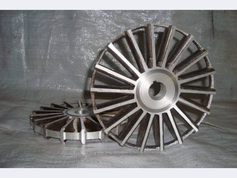
1.2 Half-closed
The difference between a half-closed product is that it does not have a second disk, and the blades with a gap adjoin the case of the device, which plays the role of the second disk. Semi-closed products are used to pump very contaminated liquids.
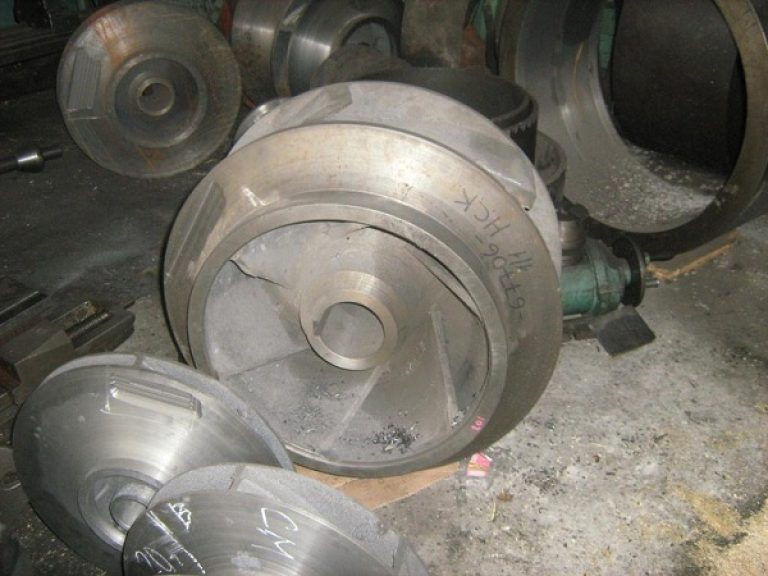
1.3 Closed
The design of the closed product has two disks, between which there are blades. Such an impeller is often used for the operation of centrifugal pumps, because it creates a good pressure, and is characterized by small leaks of water from the entrance to the entrance. Such impellers are produced in several ways: stamping, casting, spot welding or riveting. The quality and efficiency of work is affected by the number of blades. The more blades the part has, the less the pulsation of the water pressure at the outlet of the device.
1.4 Type of landing
The landing of the impeller on the motor shaft in unicycle units is conical or cylindrical. The seat of the wheels in horizontal or vertical pumping devices is in the form of a hexagon or a hexagonal sprocket, or crosswise.
The following types of landings on the shaft are distinguished:
- Cone landing. This type of landing provides an easy landing and removal of the impeller. The disadvantage of a tapered fit is the not entirely accurate position of the wheel relative to the device body in the longitudinal direction. The working part cannot be moved on the shaft, because it is rigidly fixed. The conical fit is characterized by large beats of the product, which is bad for mechanical seals and stuffing box packing.
- Cylindrical landing. With this fit, the part is in the exact position on the shaft. The impeller is fixed with a few keys. A cylindrical fit is installed in submersible vortex and vortex pump units. This connection allows you to more accurately fix the position of the impeller on the shaft. The disadvantage of a cylindrical fit is the precise machining of the instrument shaft and the holes in the impeller hub.
- Hexagonal (cruciform) landing. It is used mainly in pumping devices for pumping water from wells. With this type of fit, it is very simple to fix and remove the impeller from the mechanism shaft. At the same time, it is firmly fixed on the shaft in the axis of rotation of the mechanism. Using washers in the impeller and diffuser you can adjust the gaps.
- Landing in the form of a hexagonal star is used in multistage high-pressure pumps (vertical and horizontal). Impellers for these plants are made of stainless steel. This is the most difficult fit and requires top-notch handling. The bushings in the diffusers and impellers regulate the gaps.
1.5 Centrifugal impeller
For the manufacture of wheels for centrifugal pumps, most often they use cast iron of the SCh 20-SCh 40 grades. If the electric pump will work with chemical aggressive substances, the wheels and bodies of centrifugal pumps are made of stainless steel. For the operation of the device in complex modes, which are characterized by: a long turn-on time; material for pumping has mechanical particles; high pressure, - for the production of impellers, chrome cast iron is used.
1.7 Turning and calculation of the impeller of a centrifugal pump
By turning the wheels, the diameter is reduced to reduce the pressure force, but the hydraulic efficiency of the device does not deteriorate. With a small decrease in efficiency, the pressure and flow rises very significantly.
If the characteristics of the device do not meet the necessary working conditions within certain limits, it is worthwhile to use turning. The number of threads from the manufacturer, as a rule, is not more than two. The size of the turning varies from 8 to 15% of the diameter of the workpiece. But there are exceptions when the indicator can be increased to 20%.
Calculation of the impeller of a centrifugal device is not recommended to do on their own - this is a responsible process that is best performed by a specialist.
2 Description of an open impeller centrifugal pump
Open type impellers are equipped with both drainage and fecal devices. Wheels of this type can be installed above the working chamber of the unit and inside the chamber. When installed above the chamber, large particles can pass freely, therefore this scheme is called a free-vortex.
![]()
Along with this advantage, there are a number of disadvantages:
- Decrease in efficiency.
- The need to install a more powerful engine.
- Low fluid pressure.
It is not practical to install a free-vortex scheme in drainage units, since they were originally intended for pumping liquid with inclusions. In such devices, the impeller is placed inside the working chamber. There are several types of open wheels:
- with small blades (in height), which are used for installation in drainage mechanisms or in devices with a free-swirl scheme;
- with high blades, which are used in fecal pumps. The characteristics of such a wheel allow it to be installed where free passage of particles and a greater pressure are necessary than when working with a free-vortex scheme.
Mostly open impeller with one blade is used in units with a cutting mechanism, when the edge of the device plays the role of a knife. On the suction cover there are star-shaped edges that serve as fixed knives. The device performs two functions at once: pumping water with large particles and grinding long-fiber inclusions. This allows you to work with such liquids without risking clogging the device.
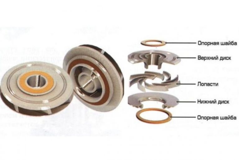
2.1 Submersible pump with peripheral impeller
A peripheral impeller is used to supply water from wells with a minimum diameter of 4 ’’ (100 mm). Such mechanisms work with liquid without solid inclusions and precipitation.
The wheel is made of brass or bronze. A feature of such devices is the presence of radial blades on the periphery of the impeller, which transmit the energy of the pumped medium. The product is installed between two plates that are made of stainless steel.
With a cylindrical fit, small gaps are created inside the working chamber of the device. The design of the blades provides a radial circulation of the fluid that enters the unit between the plates and the impeller blades. This allows you to gradually increase the pressure of the water as it moves from the intake pipe to the outlet. The wheel itself is mounted on stainless steel shaft.
2.2 Impeller of the pump 1СВН 80 А
Units 80 A are designed for pumping clean liquids: water, fuels and lubricants, diesel fuel, gasoline, etc. The 80 A mechanism is installed in fuel trucks, tankers and similar types of equipment. The drive mechanism 80 A comes from the power take-off shaft, or from the electric motor through the power take-off and transmission. The flow part is made of aluminum alloy.
The working part has radial blades and is located in a closed case of a cylindrical mechanism. There are end gaps between the housing and the impeller.
Specifications 80 A:
- head - 32 m;
- rotation speed - 1450 rpm;
- suction height - up to 6.5 m;
- power - 9 kW.
2.3 Replacing the main workpiece
If the element is made poorly, there is an uneven load on the entire device, which can lead to an imbalance in the flow parts. And this, most often, leads to a breakdown of the rotor. If such a breakdown occurs, the impeller must be replaced.
The impeller is replaced as follows:
- The pump part is disassembled.
- Wheel or wheels vary (depending on design).
- Inspection and verification of the remaining parts of the unit.
- The device is assembled and tested by the load.
With proper installation and observance of the operating rules, the impeller, like the pump unit itself, can last a long time and do its job for many years.